Trip Devices for Circuit Breakers

A technology for tripping devices and circuit breakers, which is applied to emergency protection devices, circuits, and components of protective switches to achieve the effects of increased tripping speed, increased energy gain, and short tripping time

Active Publication Date: 2014-10-22
SIEMENS AG
View PDF3 Cites 0 Cited by
  • Summary
  • Abstract
  • Description
  • Claims
  • Application Information

AI Technical Summary

Problems solved by technology

[0006]The switching times required by current circuit breakers can sometimes no longer be achieved with the solutions known from the prior art
At the same time a low energy actuator is required to actuate the trip detent, which also limits the spring force

Method used


Image

  • Trip Devices for Circuit Breakers
  • Trip Devices for Circuit Breakers
  • Trip Devices for Circuit Breakers

Examples


Embodiment Construction

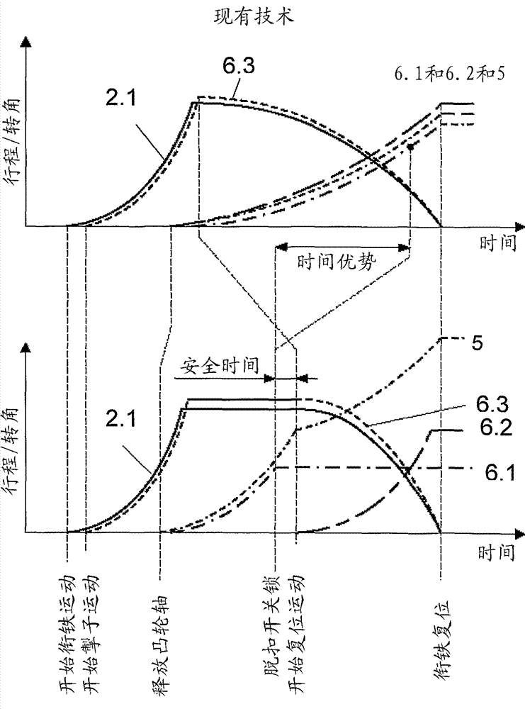
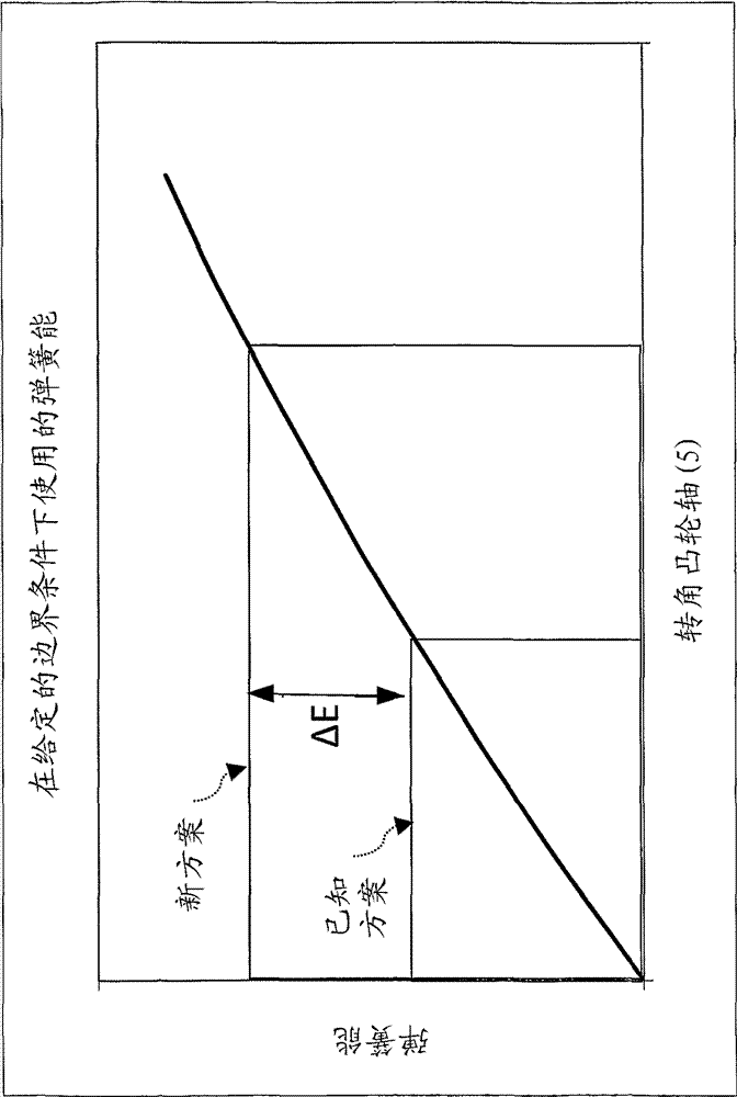
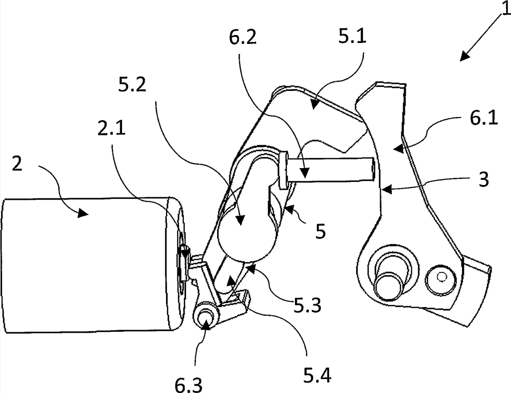
[0039] Figures 1 to 3The initial, intermediate and final positions of the same tripping device 1 , in particular for a circuit breaker, are shown in a perspective view. The tripping device 1 according to the invention comprises a controllable tripping magnet 2 with an armature 2.1, which is operatively connected to a rear-mounted tripping catch 6.3, which engages with a tripping mechanism acting on the circuit breaker , the tripping mechanism is coupled to the pretensioned spring 4 as a force amplifier. According to the invention, a camshaft 5 with a plurality of cams 5.1, 5.2, 5.4 is provided as tripping mechanism. Each of the cams 5.1, 5.2 and 5.4 positioned on the camshaft 5 with offset angles of rotation is assigned an actuating mechanism 6, wherein in the event of tripping at least two of the associated actuating mechanisms 6.1, 6.2, 6.3 are operated sequentially in time. The adjustment process, whereby in order to complete the subordinate adjustment process, the entir...


PUM


Abstract

At least one embodiment of the invention relates to a tripping apparatus, particularly for circuit breakers, which includes at least one controllable tripping magnet having an armature that is operatively connected to a downstream tripping gear, which engages in a tripping mechanism that acts on the circuit breaker and is coupled to a preloaded spring serving as a force amplifier. According to at least one embodiment of the invention, the tripping mechanism includes a camshaft having a plurality of cam lobes, wherein at least one actuating device is associated with each cam lobe having an offset rotational angle, and wherein, when tripped, at least two actuating processes associated with the respective actuating means take place consecutively, so that the full spring force is transmitted by way of the camshaft to at least one of said actuating means so as to perform the relevant actuating process.

Description

technical field [0001] The invention relates to a tripping device, in particular for a circuit breaker, which has at least one controllable tripping magnet with an armature, which is operatively connected to a rear-mounted tripping catch, which acts on the circuit breaker. The release mechanism on the device is engaged, and the release mechanism is coupled with a pre-tensioned spring as a force amplifier. Background technique [0002] This trip unit with force amplification is used to operate circuit breakers. Circuit breakers designed for large currents can not only switch operating currents and small overload currents, but can also switch on large overload currents and short-circuit currents in the event of a fault, and this fault current is maintained for a given time and then disconnected. Overcurrents relate to the weakest link of the installation placed behind the circuit breaker as seen in the direction of energy flow. In order to protect the downstream equipment a...

Claims


Application Information

Patent Timeline
Patent Type & Authority Patents(China)
IPC IPC(8): H01H71/10H01H71/44H01H71/50
CPCH01H71/1072H01H3/3031H01H71/505H01H71/44H01H71/46
Inventor M.库尔克J.加斯曼T.米勒
Owner SIEMENS AG
Why Eureka
Try Eureka