Unlock instant, AI-driven research and patent intelligence for your innovation.
lever switch valve
What is Al technical title?
Al technical title is built by PatSnap Al team. It summarizes the technical point description of the patent document.
A switching valve and lever-type technology, which is applied in the direction of valve details, multi-way valves, valve devices, etc., can solve the problems of switching valve switching force, long stroke, discomfort, etc., to improve resistance, save travel, and eliminate water resistance Effect
Active Publication Date: 2016-10-05
ZHANGZHOU SOLEX SMART HOME CO LTD
View PDF8 Cites 2 Cited by
Summary
Abstract
Description
Claims
Application Information
AI Technical Summary
This helps you quickly interpret patents by identifying the three key elements:
Problems solved by technology
Method used
Benefits of technology
Problems solved by technology
[0003] Aiming at the inconvenience and discomfort caused by the large switching force and long stroke of the existing switching valve, the present invention proposes a lever type switching valve, and its technical solution is as follows:
Method used
Image
Click on the blue label to locate the original text in one second.
Reading with bidirectional positioning of images and text.
Examples
Embodiment 1
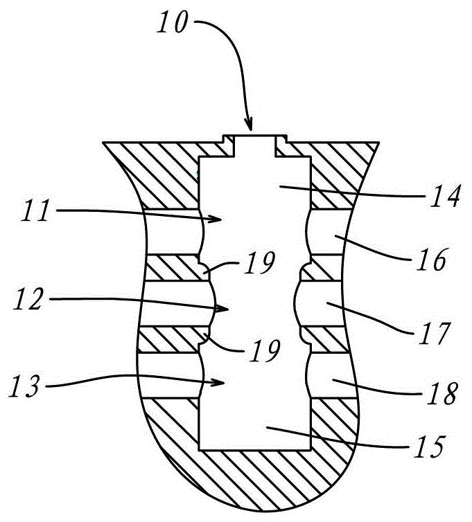
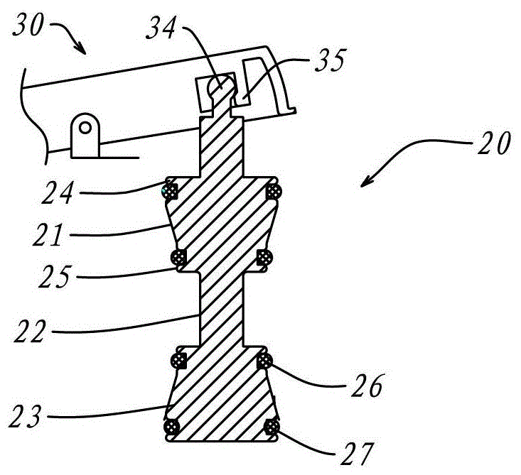
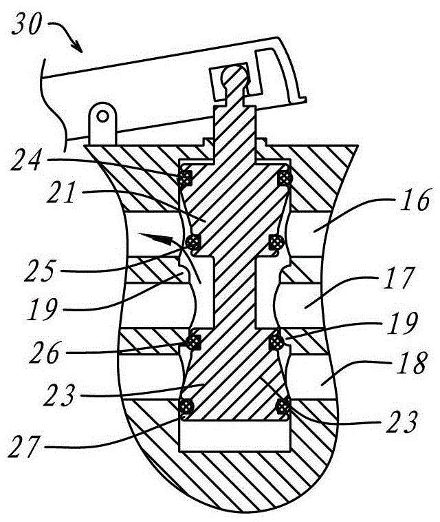
[0030] Such as Figure 1 to Figure 3 Shown, a series of schematic diagrams of Embodiment 1 of the present invention, wherein figure 1 is the configuration of the switching cavity 10, figure 2 It is the structure of movable bolt 20, image 3 is a schematic diagram of the device assembly.
[0031] Such as figure 1 , the switching chamber 10 is divided into three sections according to its axial direction, which are respectively the water outlet chambers 11, 13 at both ends and the water inlet chamber 12 in the middle section; the respective axial outer ends of the water outlet chambers 11, 13 each have a sliding section 14, 15 There is an inner convex ring 19 between both ends of the water inlet chamber 12 and the water outlet chambers 11 and 13; the water inlet chamber 12 is connected to a water inlet 17;
[0032] Such as figure 2 , the movable bolt 20 is dumbbell-shaped, and also includes three sections according to its axial direction, which are respectively pistons 21,...
Embodiment 2
[0041] Such as Figure 4 to Figure 6 Shown, the schematic diagram of embodiment two of the present invention; Wherein Figure 4 It is a sectional view of the switching cavity 10 and the housing 40 where it is located; Figure 5 is a schematic cross-sectional view of the movable bolt 20; Figure 6 It is an overall sectional view of the embodiment installed in a valve body 1 .
[0042] Such as Figure 4 As shown, the shape and structure of the switching cavity 10 in this embodiment are the same as those in Embodiment 1, so details are not repeated here. The switching chamber 10 is located in a cylindrical housing 40; the outer wall of the housing 40 has three water holes 41, 43 and 42 distributed axially, corresponding to the water inlet and two water outlets respectively, that is, having the same function.
[0043] Such as Figure 5 As shown, the sectional view of the movable plug 20 of the present embodiment, the pistons 21, 23 and the water passing section 22 of the mova...
PUM
Abstract
The invention discloses a lever switching valve, which is characterized by comprising a switching cavity and a movable pin, and the switching cavity is axially provided with water outlet cavities at both ends and a water inlet cavity in the middle section; the outer end of each water outlet cavity is provided with a sliding section, and an inner convex ring is arranged between the two ends of the water inlet cavity and the water outlet cavity; the movable pin is in a dumbbell shape, is axially fit into the switching cavity, and is axially provided with pistons at both ends and a water passing section, and the water passing section is connected into the inner convex ring in a penetrating way; a water passing channel is arranged between the water passing section and the inner convex ring, and one end of the movable pin is movably fit to a lever; when the inner end of one piston in the water outlet cavity is in seal fit to the inner convex ring at the corresponding side, a waterway between the water outlet cavity and the water inlet cavity is blocked, and meanwhile, the water inlet cavity at the other side is communicated with the water inlet cavity through a waterway between the water passing section and the inner convex ring. The lever switching scheme with laborsaving switching, balanced switching force, and shorter stroke of movable pin is realized.
Description
technical field [0001] The invention relates to a switching valve, in particular to a switching valve operated on the principle of leverage. Background technique [0002] The existing axial pull-type switching valves usually use the pull head as the operating part to control the switching of the waterway. It is about to control between one input waterway and two output waterways to realize the conduction of the input waterway switching ground and the output waterway. The existing axial pull-type switching valve has several obvious defects: first, because of the influence of water flow and air pressure on switching movable parts, the required switching force is very large when switching; second, because the moving parts require Only by sliding can the switching waterway be connected, and the switching stroke is relatively long; based on the above two reasons, the existing axial pull-type switching valve is not convenient enough, and the operation is uncomfortable and smooth....
Claims
Application Information
Patent Timeline
Application Date:The date an application was filed.
Publication Date:The date a patent or application was officially published.
First Publication Date:The earliest publication date of a patent with the same application number.
Issue Date:Publication date of the patent grant document.
PCT Entry Date:The Entry date of PCT National Phase.
Estimated Expiry Date:The statutory expiry date of a patent right according to the Patent Law, and it is the longest term of protection that the patent right can achieve without the termination of the patent right due to other reasons(Term extension factor has been taken into account ).
Invalid Date:Actual expiry date is based on effective date or publication date of legal transaction data of invalid patent.

