Explosive Water Jet with Precursor Bubble

a water jet and precursor technology, applied in the direction of dislodging machines, transportation and packaging, lighting and heating apparatus, etc., can solve the problem of prohibitive power consumption of significantly larger jets, and achieve the effect of removing water resistan

Inactive Publication Date: 2009-02-05
UNITED STATES OF AMERICA NAVAL UNDERSEA WARFARE CENT DIV NEWPORT OFFICE OF COUNSEL THE
View PDF4 Cites 2 Cited by
  • Summary
  • Abstract
  • Description
  • Claims
  • Application Information

AI Technical Summary

Benefits of technology

[0011]It is a further object of the present invention to provide an assembly and method of use for creating a gas bubble at the water jet discharge nozzle through which high velocity water is expelled as a cutting system that overcomes the jet formation inhibiting effects of water as a surrounding medium.
[0017]Generally, the proposed water jet assembly and method of use overcomes difficulties with traditionally-used steady cutting jets and the pulsed difficulties of the jet described in U.S. Pat. No. 6,868,790 (incorporated herein by reference) by venting combustion gases immediately prior to the water jet in order to eliminate water resistance.

Problems solved by technology

Power consumption for significantly larger jets becomes prohibitive if sustained operation is required.

Method used


Image

  • Explosive Water Jet with Precursor Bubble
  • Explosive Water Jet with Precursor Bubble
  • Explosive Water Jet with Precursor Bubble

Examples


Embodiment Construction

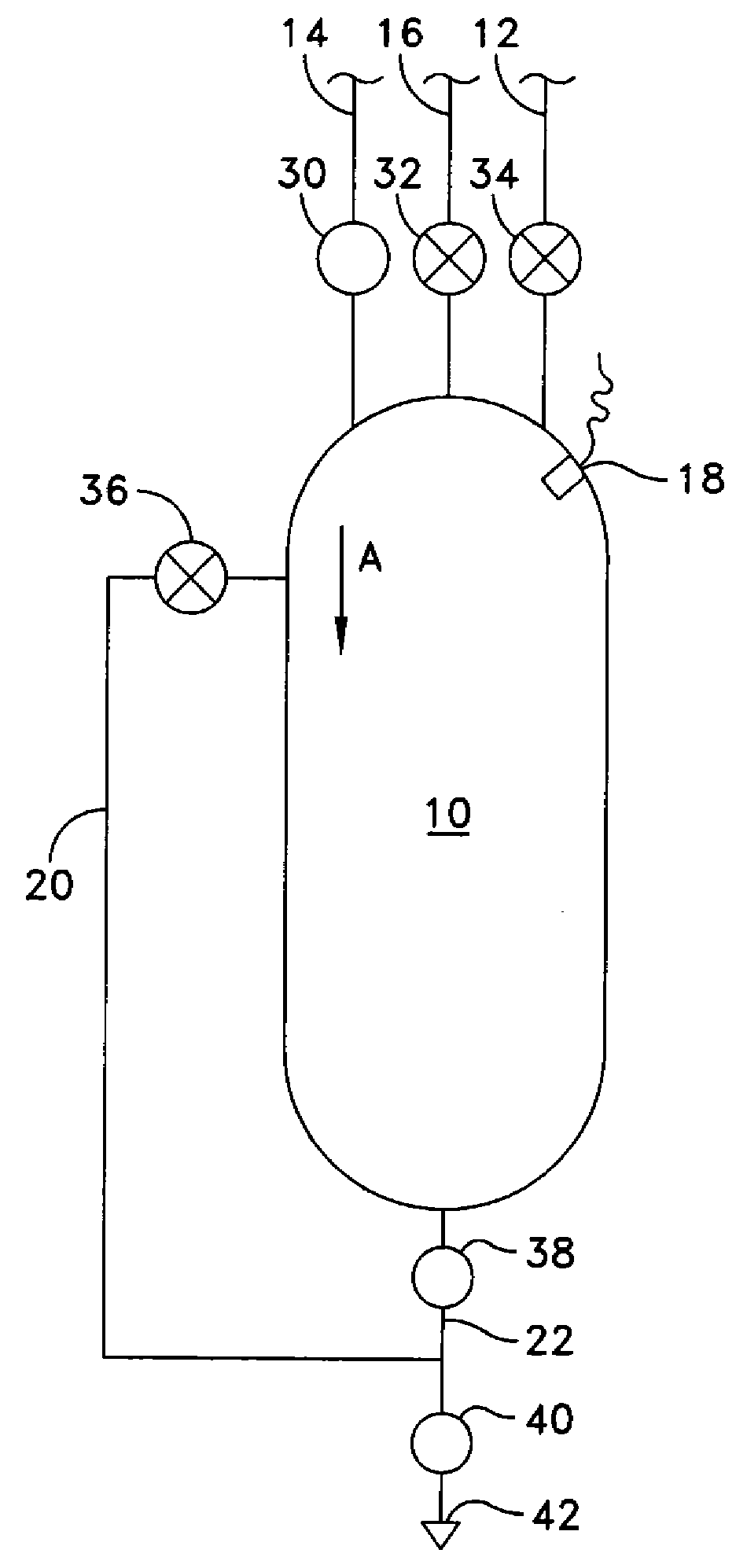
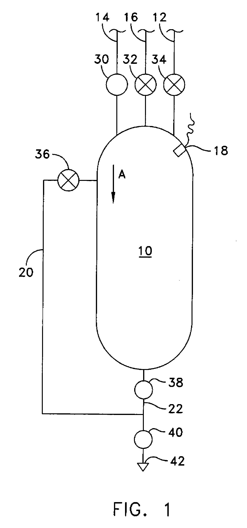
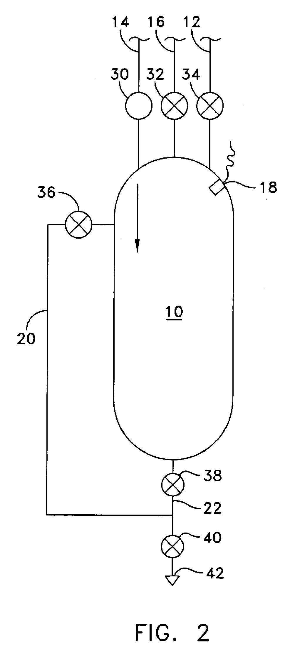
[0028]FIG. 1 through FIG. 8 illustrate the operation of the water jet system of the present invention. The system consists of a tank 10, a water feed line 12, an oxidizer line 14, a fuel line 16, a spark generator 18, a gas vent 20, a discharge line 22 and control valves 30, 32, 34, 36, 38, 40.

[0029]In operation, the tank 10 is purged by the oxidizer line 14 using a gaseous oxidizer—such as air. As shown in FIG. 1, any residual combustion gas and liquid is forced out of the tank 10 in direction “A” through the discharge valves 38, 40 and a nozzle 42 by using the oxidizer supplied by the oxidizer line 14 (See Table 1 for valve sequencing).

[0030]The control valves 38, 40 are then closed and the tank 10 is filled with oxidizer (See FIG. 2). The control valve 30 is then closed and water by the water feed line 12 (or other cutting fluid) is supplied in direction “B” into the tank 10 by the opening of control valve 34, thereby compressing the oxidizer within the tank (See FIG. 3).

[0031]Wh...


PUM

PropertyMeasurementUnit
velocitiesaaaaaaaaaa
pressuresaaaaaaaaaa
diametersaaaaaaaaaa

Abstract

A water jet assembly and method of use comprising a tank with cutting fluid, fuel and oxidizer lines, and a tank discharge lines. In operation, the tank is filled with oxidizer; the oxidizer line is closed and cutting fluid is supplied compressing the oxidizer. When the fluid reaches a level, the fluid line is closed and fuel is injected. A spark generator ignites the fuel / oxidizer mixture thereby raising the tank pressure. As the pressure rises, a low pressure valve simultaneously closes at a prescribed level. The vent line and a discharge to a nozzle are opened thereby, forming a gas bubble. When the bubble reaches a desired size and pressure drops below a level, the vent closes, allowing combustion expansion to force fluid through the nozzle to form a cutting jet. The bubble allows the jet to retain coherence between the nozzle and a cutting surface.

Description

[0001]This application claims the benefit of U.S. Provisional Patent Application Ser. No. 60 / 963,207 filed on Jul. 20, 2007 and entitled “Explosive Water Jet with Precursor Bubble” by the inventor, Thomas J. Gieseke.STATEMENT OF GOVERNMENT INTEREST[0002]The invention described herein may be manufactured and used by or for the Government of the United States of America for Governmental purposes without the payment of any royalties thereon or therefore.CROSS REFERENCE TO OTHER PATENT APPLICATIONS[0003]None.BACKGROUND OF THE INVENTION[0004](1) Field of the Invention[0005]The present invention relates to an assembly and a method of use for producing a high velocity water jet in a deep-water environment where depth pressure would typically inhibit the formation of a supercavitation bubble.[0006](2) Description of the Prior Art[0007]High velocity jets are commonly used in industrial systems for cutting operations. For example: pressures of 380 Mpa (50,000 pounds per square inch), generate...

Claims


Application Information

Patent Timeline
Patent Type & Authority Applications(United States)
IPC IPC(8): B26F3/00
CPCB26F3/004F41B9/0087F41B9/0043B26F3/04Y10T137/0391Y10T83/364
Inventor GIESEKE, THOMAS J.
Owner UNITED STATES OF AMERICA NAVAL UNDERSEA WARFARE CENT DIV NEWPORT OFFICE OF COUNSEL THE
Why Eureka
Try Eureka