Drive device for a valve of a beverage filling system

A driving device and filling machine technology, applied in the direction of valve device, valve operation/release device, packaging, etc., can solve the problems of increased probability of failure, excessive energy, inaccurate filling operation, etc., to achieve large Holding force, effect of large switching operation force

Inactive Publication Date: 2014-01-15
KRONES AG
View PDF12 Cites 1 Cited by
  • Summary
  • Abstract
  • Description
  • Claims
  • Application Information

AI Technical Summary

Problems solved by technology

Differences in on-off time can lead to inaccuracies in filling operations
[0006] In addition, compressed air may be used to control the diaphragm valves and correspondingly compressed air may reach the filling area, which may be undesirable from a hygienic point of view
[0007] In addition, providing compressed air to operate pneumatic drives requires more energy
Also, two valves (i.e., a true diaphragm valve and a corresponding pilot valve) are always provided to control the respective fluid flows, and as a result, the chances of failure are increased

Method used


Image

  • Drive device for a valve of a beverage filling system
  • Drive device for a valve of a beverage filling system
  • Drive device for a valve of a beverage filling system

Examples


Embodiment Construction

[0032]Preferred embodiments will be described below with reference to the accompanying drawings. Identical, similar or identically functioning components are identified with the same reference numerals in different drawings, and a repeated description of such components is sometimes omitted in the following description to avoid redundancy.

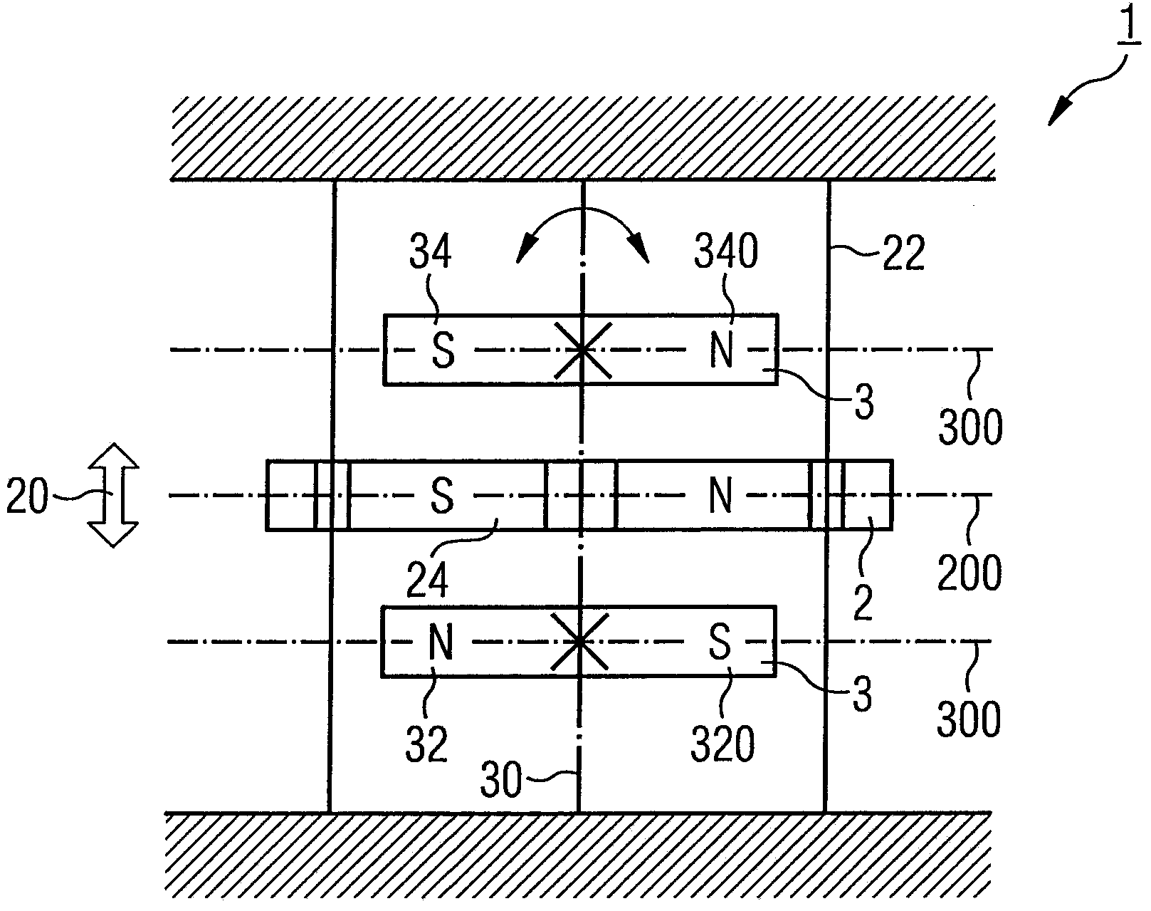
[0033] figure 1 A drive device 1 for a valve of a beverage filling machine is shown, preferably for a material valve and / or a gas valve of a filling mechanism of a beverage filling machine.

[0034] The drive device 1 comprises a movable part 2 which is linearly movable in a direction of movement 20 , the linear movement of which is used to drive the valve. Correspondingly, the movable part 2 can move linearly along the direction of movement 20 indicated by the arrow and is operatively connected to the regulating parts of the valve. in such as figure 1 In the illustrated embodiment, the movable part 2 is correspondingly guided linearly ...


PUM


Abstract

The invention provides a drive device (1) for a valve of a beverage filling system. The drive device is preferably used for a material valve or a gas valve of a filling mechanism. The drive device includes at least one movable piece (2) and at least one actuator (3). The movable piece can move in a moving direction (20) and has at least one movable piece magnet (24, 260, 280) used for driving the valve. The actuator has at least one actuator magnet (320, 340, 360) used for driving the movable piece (2) to move. The actuator (3) can move within an actuator plane (300) to cause the movable piece (2) to move. The actuator plane is configured to be perpendicular to the moving direction (20) of the movable piece (2).

Description

technical field [0001] The invention relates to a drive device for a valve of a beverage filling machine, preferably for a material valve or a gas valve of a filling mechanism of a beverage filling machine. Background technique [0002] In common beverage filling machines, valves are used in different areas to control fluid flow. In particular, a valve is arranged, for example as a material valve, in the region of the filling mechanism of the beverage filling machine for switching the material flow to the container to be filled. Also, valves are usually provided on the filling mechanism for controlling the gas. For example, when filling a container with carbonated beverages, it is usually filled with a filling gas such as CO before filling. 2 To prefill the container, in order to avoid excessive foaming of the carbonated beverage to be filled when it is filled into the container and accordingly provide a reliable, defined filling process. After such filling with a prefill...

Claims


Application Information

Patent Timeline
Patent Type & Authority Applications(China)
IPC IPC(8): B67C3/26
CPCF16K31/088B67C3/28
Inventor 弗洛里安·安格雷尔
Owner KRONES AG
Why Eureka
Try Eureka