Relay with a core having an enlarged cross-section

A technology of relays and sections, applied in relays, stepless relays, electromagnetic relays, etc.

Active Publication Date: 2004-12-01
TYCO ELECTRONICS AUSTRIA
View PDF1 Cites 1 Cited by
  • Summary
  • Abstract
  • Description
  • Claims
  • Application Information

AI Technical Summary

Problems solved by technology

[0004] A disadvantage of relays known from known references is that it is difficult to provide sufficient switching force with a compact structure

Method used


Image

  • Relay with a core having an enlarged cross-section
  • Relay with a core having an enlarged cross-section
  • Relay with a core having an enlarged cross-section

Examples


Embodiment Construction

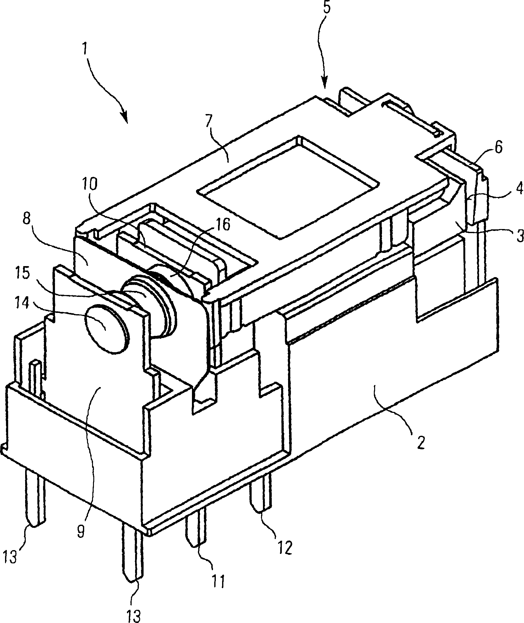
[0020] First refer to figure 1 Describe the basic structure of a relay.

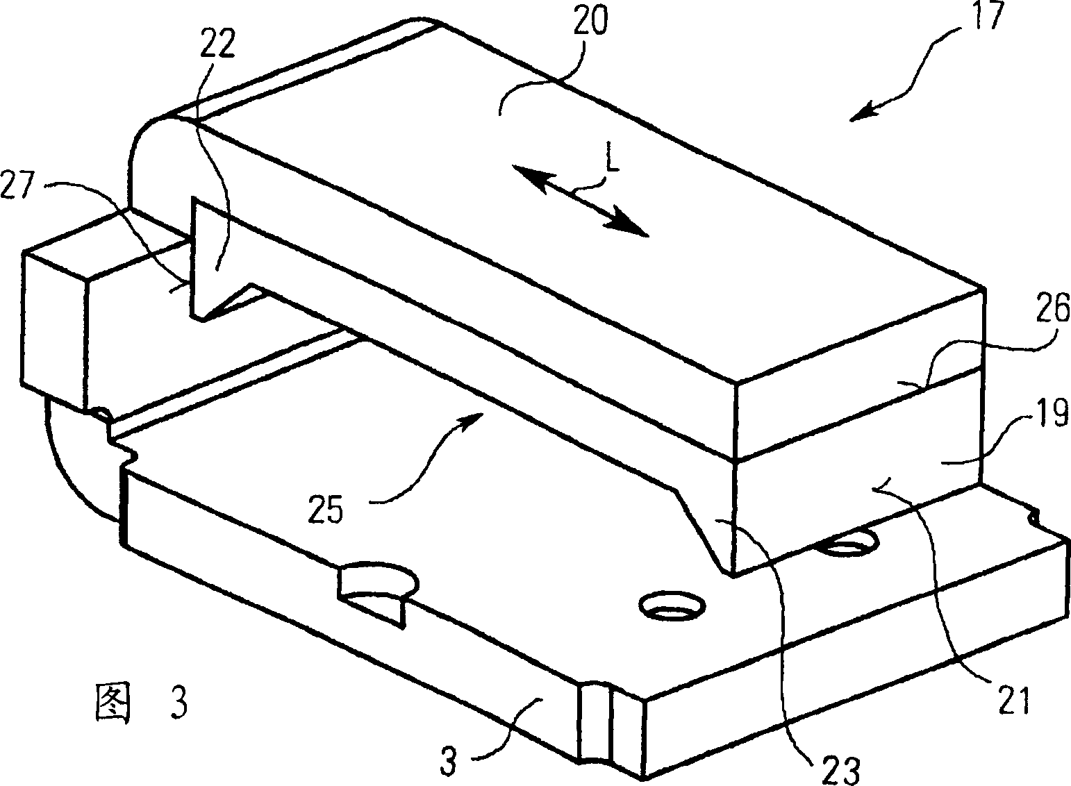
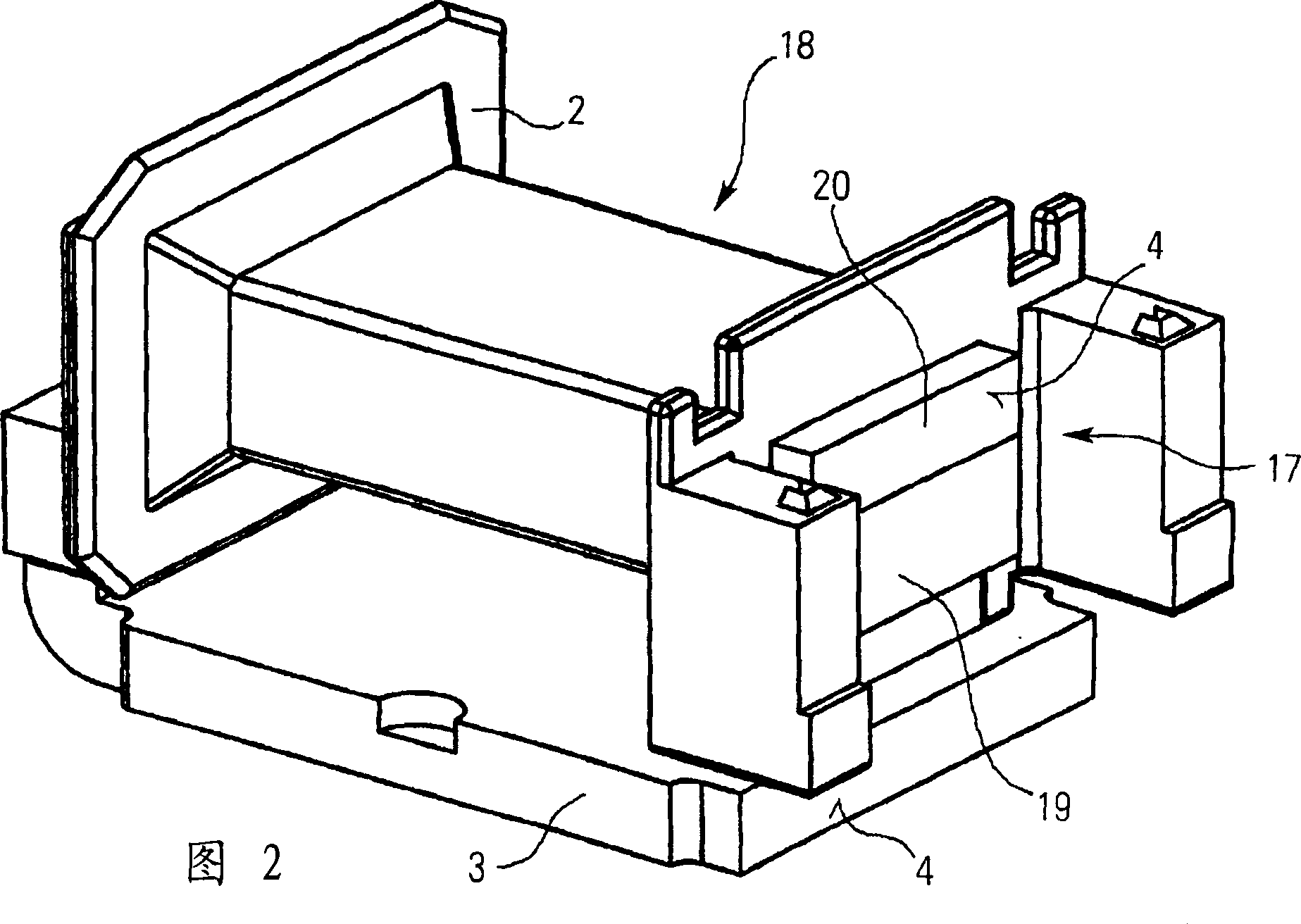
[0021] The relay 1 includes a coil wound on a bobbin 2 ( figure 1 not shown), the yoke 3 and the core passing through the bobbin 2 ( figure 1 not shown). The yoke 3 terminates in a pole face 4 which engages the working air gap 5 . In other designs, the pole face 4 can be formed on the core.

[0022] A working air gap 5 is arranged between the pole face 4 and the movable armature 6 . The armature 6 is connected to the spring contact 8 by means of a connection 7 guided along the coil former 2 in order to transmit the movement, so that the movement of the armature 6 necessarily causes the movement of the spring contact 8 .

[0023] The spring contact 8 is in turn arranged between two fixed contacts 9 and 10 which are arranged at a distance from each other in the direction of movement of the spring contacts, wherein the spring contacts can preferably be respectively Only one of the two fixed contacts 9...


PUM


Abstract

The invention relates to a relay comprising a coil bobbin, a core penetrating the coil bobbin and a yoke. To achieve a high switching force with a low overall height, the cross-sectional area of the core is greater in the region toward the transition to the yoke than in the central region of the coil bobbin. Increased magnetic flux can be conveyed from the core owing to the cross-sectional enlargement and at the same time more coil windings can be arranged in the central region owing to the reduced cross-section there. Both measures act together and allow high switching forces with low overall height.

Description

technical field [0001] The invention relates to a relay with a bobbin, a core passing through the bobbin and a yoke. Background technique [0002] Relays with the above-mentioned technical features are known, for example, from EP-A-202 651 , EP-B-363 176 , EP-B-691 667 and DE-C-42 32 228 . [0003] In all of the above relays, the bobbin, core and yoke form the magnetic system that triggers the switching process when the coil is energized or energized. During switching, the energized coil generates a magnetic switching force that moves the armature. The movement of the armature is transmitted to the spring contact, which closes (makes) or opens (breaks) electrical contact with one or more stationary contacts. [0004] A disadvantage of the relays known from the known references is that it is difficult to provide a sufficient switching force with a compact construction. Contents of the invention [0005] The object of the present invention is to improve a switching relay ...

Claims


Application Information

Patent Timeline
Patent Type & Authority Applications(China)
IPC IPC(8): H01F7/06H01H50/16H01H50/36H01H51/06
CPCH01H50/36H01H50/163
Inventor 鲁道夫·米克尔利奥波德·马德伯恩德·阿德里安约翰尼斯·赫尔姆赖克
Owner TYCO ELECTRONICS AUSTRIA
Why Eureka
Try Eureka