Monitoring device

A monitoring device and monitoring area technology, applied in transportation and packaging, closed-circuit television systems, instruments, etc., can solve problems such as narrowing of the area, difficulty in correctly judging the monitoring area, and misjudgment as congestion.

Inactive Publication Date: 2012-01-11
HITACHI LTD
View PDF6 Cites 12 Cited by
  • Summary
  • Abstract
  • Description
  • Claims
  • Application Information

AI Technical Summary

Problems solved by technology

For example, if there is one person on the entrance and exit platform of an escalator, and the shadow of this one person is very long, the area of ​​the background difference becomes larger due to the influence of the shadow. In fact, the passenger is free for one person, but it may be misunderstood. Judged as crowded
Also, when the shadows of structures such as handrails are long, even though there is no passenger on the entrance / exit platform, the area of ​​the background difference becomes larger due to the shadows of structures such as handrails. In this case, actually Not even one passenger is free, but it may be misjudged as crowded
Therefore, in the technique disclosed in Patent Document 1, it is impossible to accurately determine whether the number of people in the monitoring area is 0, 1, or 2 or more.
[0018] In addition, when using another criterion disclosed in Patent Document 1, that is, the criterion that the larger the area of ​​the difference between frames is, the higher the degree of congestion is, for example, when a passenger falls and tries to get up, the passenger may The area of ​​the difference between the frames becomes larger due to the movement of the frame, and it may happen that there is actually only one passenger idle, but it is misjudged as a crowded situation
Also, in contrast to this, in the case where many passengers cannot move due to extreme crowding, the area of ​​the difference between frames becomes narrow because the movements of the passengers are small, and it is actually crowded because there are many people, but there is still May be falsely identified as idle
Therefore, when the technology disclosed in Patent Document 1 is applied to the estimation of the number of people, since it is impossible to distinguish between a situation with few passengers and a situation with many passengers, it is impossible to accurately determine whether the number of people in the monitoring area is 0, 1, or 2. above
[0019] Based on the above reasons, it is difficult to correctly judge whether the number of people in the surveillance area is 0, 1, or more than 2 people using the technology of Patent Document 1
[0020] On the other hand, the above-mentioned Non-Patent Documents 1 and 2 are very good technologies such as person recognition technology for distinguishing the movement of people from the action of the escalator, but they do not distinguish between 0 people, 1 person, or 2 or more people This classification assumes that the number of people in the surveillance area is estimated, and it does not take into account the number of people in the surveillance area to reduce the alarm when there are no persons in the background image, etc.

Method used


Image

  • Monitoring device
  • Monitoring device
  • Monitoring device

Examples


no. 1 example

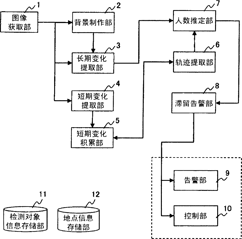
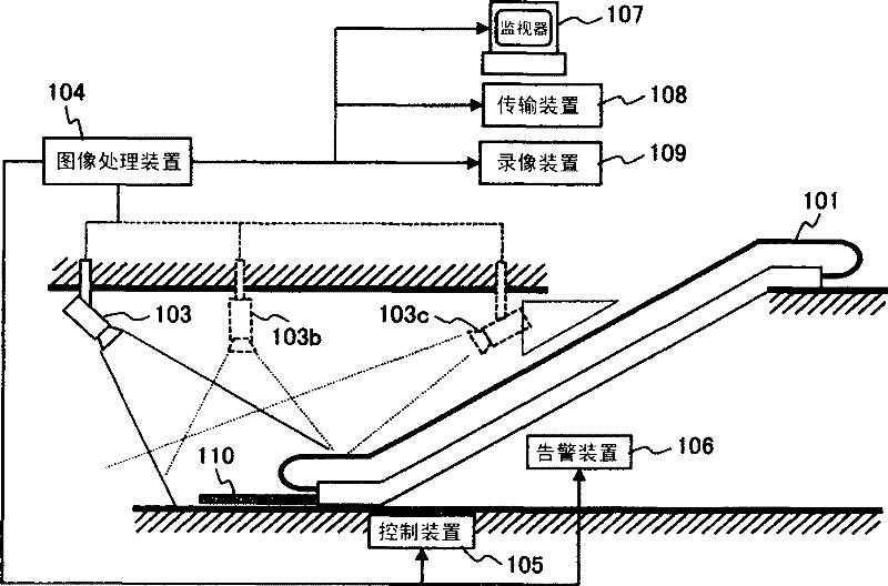
[0063] figure 1 is a functional block diagram of the monitoring device according to the first embodiment of the present invention. figure 2 It is a device configuration diagram when used as an escalator monitoring device. In the first embodiment, the entrance and exit platform of the escalator is used as the monitoring area, and the stagnation of people near the moving pedals and handrails during the operation of the escalator is regarded as actions that may cause accidents involving the pedals and handrails, etc., and Make it the object of detection.

[0064] exist figure 2 Among them, 101 represents an escalator, 110 represents the entrance and exit platform of the lower part of the escalator, 103 represents the camera around the entrance and exit platform 110 in the field of view from the rear of the entrance and exit platform 110, 104 represents an image processing device, and 105 represents the escalator 101. The control device, 106 represents the alarm device that s...

no. 2 example

[0126] Figure 13 is a functional block diagram of the second embodiment of the present invention. exist Figure 13 Among them, the image acquisition unit 1, the trajectory extraction unit 6, the number of people estimation unit 7, the stay warning unit 8, the warning unit 9, the control unit 10, the detection object information storage unit 11 and the location information storage unit 12 play the same functions as those of the first embodiment. Function. Figure 14 Shows an example of the device structure when it is applied to an escalator.

[0127] Such as Figure 14 As shown, the sensor 203 is a sensor that can detect the presence or absence of a person 113 according to a specific measurement method, and output information related to the location of the person 113 near the entrance and exit platform 110, and its sensing range covers at least a part of the entrance and exit platform 110, And output signals with a specified duty cycle.

[0128] exist Figure 13 Among th...

no. 3 example

[0135] Figure 16 The device configuration of the monitoring device according to the third embodiment of the present invention is shown. exist Figure 16 Among them, 381 represents the door set on the channel 383, 382 represents the authentication device set on the door 381, 310 represents the monitoring area set near the door 381 and the authentication device 382, ​​and 103 represents the shooting around the monitoring area 310 within its field of view 105 and 106 respectively represent the control device and the warning device arranged beside the door 381, 104 represents the image processing device, 107 represents the monitor, 108 represents the transmission device, and 109 represents the video recording device. exist Figure 16 Among them, 113 represents a character walking on the passage 383 .

[0136] exist Figure 16 Among them, the door 381 controls the passage of the person 113 by opening and closing, and the authentication device 382 authenticates the person throu...


PUM


Abstract

The invention provides a monitoring device, which is applied for effective monitor by determining the delay population which is significant for safety management and security. The monitoring device comprises an image acquiring unit (1) for acquiring images adjacent to a monitoring area, a delay detecting unit having a background making part (2), a long-term change extracting part (3), a short-term change extracting part (4) and a short-term change accumulating part (5); a track extracting part (6) for extracting motion track from the short-term changes in the time sequence or from the time sequence storage information extracted from the short-term changes; a population judging part (7) for judging whether the number of detected persons inside the monitoring area is one or more than more according to the delay and motion track generating time and generating places; and a delay warning part (8) for warning after a determination that one person is delayed inside the monitoring area and thus effectively monitoring the person.

Description

technical field [0001] The present invention relates to a surveillance device that acquires images within a surveillance area using a surveillance camera or the like, and notifies a monitor or the like after processing the acquired images. Background technique [0002] In order to reduce the burden on the monitors who perform safety checks by observing the surveillance cameras with the naked eye, image recognition is performed on the captured images to detect abnormal behaviors such as behaviors of people and dangerous behaviors that may cause accidents at the time of the accident, and notify the monitors Alarm monitoring systems are gaining popularity. [0003] The abnormal behavior in which the person in the above-mentioned abnormal behavior has been staying in a specific place, for example, for a surveillance system for the purpose of safety management, may mean that the person is in a state of immobility due to an accident or injury, while for a surveillance system for t...

Claims


Application Information

Patent Timeline
IPC IPC(8): B66B29/00H04N7/18G06K9/00
Inventor 弓场龙三好雅则藤吉弘亘
Owner HITACHI LTD
Why Eureka
Try Eureka