Microchannel parallel-flow heat exchanger

A parallel flow heat exchanger, micro-channel technology, applied in the direction of heat exchanger shell, heat exchange equipment, evaporator/condenser, etc., can solve the problem of poor uniformity of porous flat tubes, affecting the uniformity of refrigerant distribution, The problem of poor uniformity of refrigerant distribution, etc., to achieve the effect of appropriate proportion, uniform distribution, and reasonable distribution

Inactive Publication Date: 2012-01-11
GUANGDONG MIDEA ELECTRIC APPLIANCES CO LTD
View PDF8 Cites 18 Cited by
  • Summary
  • Abstract
  • Description
  • Claims
  • Application Information

AI Technical Summary

Problems solved by technology

Causes poor uniformity of refrigerant distribution in the header
Furthermore, the uniformity of distribution in the porous flat tube is not good
3. Only consider that the refrigerant enters from the end of the inserted circular tube, which affects the uniformity of the refrigerant distribution in the inserted circular tube, which in turn affects the uniformity of the refrigerant distribution in the header and the porous flat tube

Method used


Image

  • Microchannel parallel-flow heat exchanger
  • Microchannel parallel-flow heat exchanger
  • Microchannel parallel-flow heat exchanger

Examples


no. 1 example

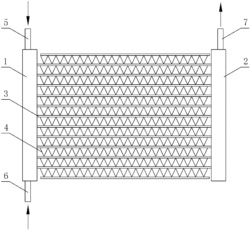
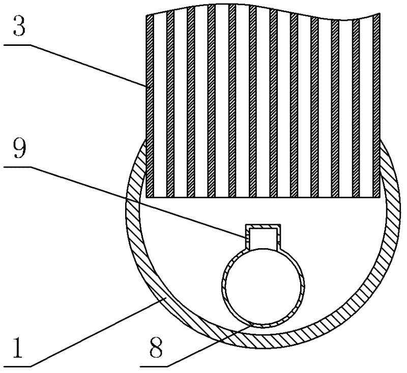
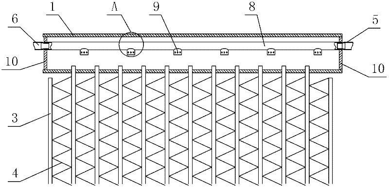
[0036] see Figure 1-Figure 4 , the micro-channel parallel flow heat exchanger includes an inlet header 1, an outlet header 2, and a refrigerant inlet pipe 8 arranged in the inlet header 1; the ends of the inlet and outlet headers are provided with More than two porous flat tubes 3 are arranged between the end cap 10 and the inlet and outlet headers, and the two ends of the porous flat tubes 3 are respectively inserted into the inlet and outlet headers. The outer periphery of the refrigerant inlet pipe 8 is provided with more than two connecting pipes 9 , and the connecting pipes 9 communicate with the inner chamber of the refrigerant inlet pipe 8 and the inner chamber of the inlet header 1 . The connecting pipe 9 is arranged on one side of the outer periphery of the refrigerant inlet pipe 8 and arranged linearly along the axial direction of the refrigerant inlet pipe 8 . The end face of the connecting pipe 9 faces the end face of the porous flat tube 3 .

[0037] The inlet ...

no. 2 example

[0041] see Figure 5 and Figure 6 , the end face of the connecting pipe 9 faces away from the end face of the porous flat tube 3, so as to prevent the refrigerant from spraying out from the split hole on the connecting pipe 9, and directly spray into the porous flat tube 3. Other unmentioned parts are the same as the first embodiment.

no. 3 example

[0043] see Figure 7 and Figure 8 , the connecting pipes 9 are arranged on the left and right sides of the periphery of the refrigerant inlet pipe 8, and more than two connecting pipes 9 on each side are provided to form two rows of connecting pipes 9; each row of connecting pipes 9 is arranged along the axial direction of the refrigerant inlet pipe 8 The directions are arranged in a straight line; wherein, the connecting pipes 9 on the left and right rows are arranged symmetrically. Wherein, the included angle between the axes of the connecting pipes 9 on the left and right sides is 180 degrees; the included angle between the axis of the connecting pipe 9 and the axis of the porous flat tube 3 is 0-90 degrees. The axis of the connecting pipe 9 and the axis of the porous flat tube 4 form an included angle of 90 degrees.

[0044] Refer to Figure 9 , the connecting pipes 9 on the left and right rows are arranged in a staggered manner.

[0045] Other unmentioned parts are t...


PUM


Abstract

The invention discloses a microchannel parallel-flow heat exchanger, which comprises an inlet flow collecting tube, an outlet flow collecting tube and a refrigerant inlet tube, wherein the refrigerant inlet tube is arranged in the inlet flow collecting tube; the end parts of the inlet flow collecting tube and the outlet flow collecting tube are both provided with end covers; more than two porous flat tubes are arranged between the inlet flow collecting tube and the outlet flow collecting tube; two ends of each porous flat tube are respectively inserted into the inlet flow collecting tube and the outlet flow collecting tube; at least one end of the refrigerant inlet tube extends out of the inlet flow collecting tube through refrigerant input tubes; the periphery of the refrigerant inlet tube is provided with more than two connecting tubes; and the connecting tubes are communicated with an inner cavity of the refrigerant inlet tube and an inner cavity of the inlet flow collecting tube. A strip flute-shaped tubular refrigerant distributor is formed in the microchannel parallel-flow heat exchanger provided by the invention; a refrigerant enters the refrigerant inlet tube from the refrigerant input tubes at two ends of the inlet flow collecting tube; and the refrigerant is uniformly distributed in the inlet tube. The refrigerant enters the inlet flow collecting tube through flow distributing hole groups on the connecting tubes on the inlet tube. The microchannel parallel-flow heat exchanger has high integral heat exchange efficiency, and the refrigerant can be uniformly distributed in a plurality of porous flat tubes.

Description

technical field [0001] The invention relates to a heat exchanger, in particular to a microchannel parallel flow heat exchanger used as an evaporator. Background technique [0002] Micro-channel parallel flow heat exchanger, a new type of heat exchanger, has gradually been more and more widely used in air-conditioning systems because of its high heat transfer efficiency. In view of the structure of the microchannel parallel flow heat exchanger: two parallel headers on both sides, the two headers are connected by a plurality of porous flat tubes for heat exchange, and there are fins for heat exchange between the porous flat tubes . When the micro-channel parallel flow heat exchanger works as an evaporator, the refrigerant used to conduct heat or cooling needs to be distributed from the inner cavity of the header to multiple porous flat tubes connected to the header. In the prior art, holes are often directly drilled on the header, so that the refrigerant first fills the cavi...

Claims


Application Information

Patent Timeline
Patent Type & Authority Applications(China)
IPC IPC(8): F25B39/00
CPCF28F9/0273
Inventor 黄小军程志明李丰
Owner GUANGDONG MIDEA ELECTRIC APPLIANCES CO LTD
Why Eureka
Try Eureka