Progressive power eyeglass lens and design method thereof

A technology of spectacle lenses and design methods, applied in the directions of glasses/goggles, optics, optical components, etc., can solve problems such as narrowing of the progressive part and near vision area

Inactive Publication Date: 2012-01-11
HOYA LENS MFG PHILIPPINES INC
View PDF6 Cites 12 Cited by
  • Summary
  • Abstract
  • Description
  • Claims
  • Application Information

AI Technical Summary

Problems solved by technology

[0017] In Patent Document 3, the regions of astigmatism are intentionally shifted on both surfaces, and therefore, the same as Figure 24 and Figure 26 The situation shown is the same, but there are disadvantages such as narrowing of the clear vision area of ​​the progressive part and the near part

Method used


Image

  • Progressive power eyeglass lens and design method thereof
  • Progressive power eyeglass lens and design method thereof
  • Progressive power eyeglass lens and design method thereof

Examples


Embodiment 1

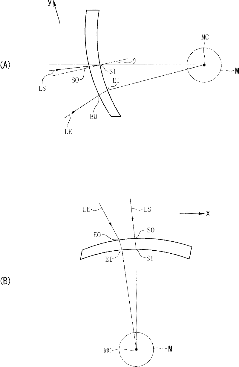
[0105] Assume normal wearing condition (10° forward tilt and 0° bend)

[0106] positive lens

[0107] prescription:

[0108] S=+3.00 ADD=1.75 prism=3.00 prism diopter

[0109] Prism base direction = 0°

[0110] Center thickness: 6.6mm

[0111] Object side faces:

[0112] Far curve = 6 Near curve = 5 Surface addition = -1.00 diopters

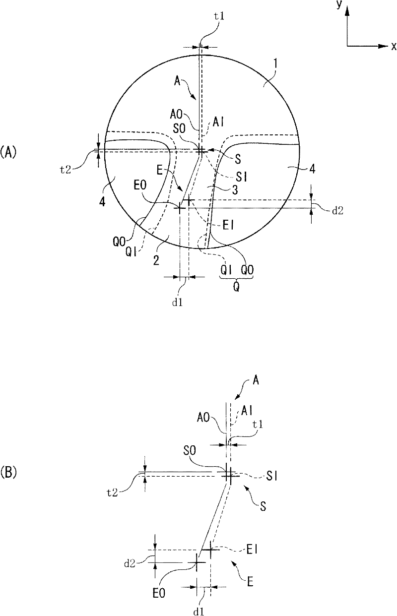
[0113] Progressive start point SO(x, y)=(0.00mm, 0.00mm)

[0114] Progressive end point EO (x, y) = (-2.50mm, -14.00mm)

[0115] The side of the eyeball:

[0116] Far curve = 3 Near curve = 0 Surface addition = +3.00 diopters

[0117] Progressive starting point SI (x, y) = (0.11mm, -0.61mm)

[0118] Progressive end point EI (x, y) = (-2.06mm, -12.67mm)

[0119] In addition, the coordinates of the matching point are set to the origin (0, 0).

[0120] Tables 1 to 3 describe the above setting conditions.

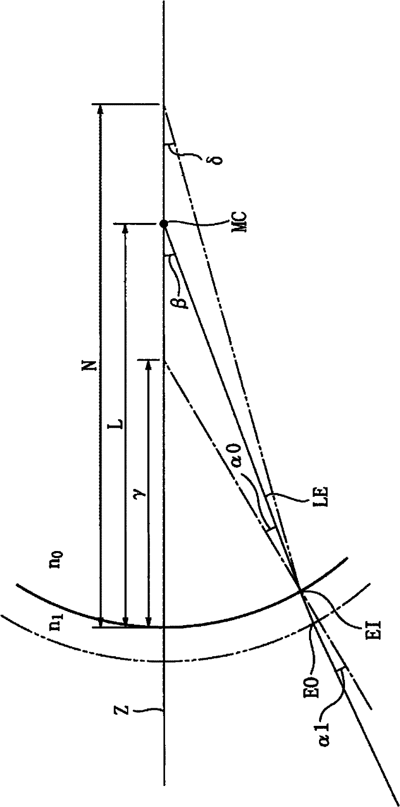
[0121] Design the gradual start point SO and the gradual end point EO of the surface arranged on the object side according to the con...

Embodiment 2

[0125] Assume a wearing state with a forward inclination angle of 20° and a bending angle of 0°

[0126] Positive lens prescription is identical with embodiment 1.

[0127] The setting of the surface on the object side is the same as in Example 1.

[0128] The setting of the surface on the eyeball side is the same as that of the first embodiment except for the coordinates of the gradual start point SI and the gradual end point EI.

[0129] Progressive starting point SI (x, y) = (0.11mm, -1.25mm)

[0130] Progressive end point EI (x, y) = (-2.05mm, -13.27mm)

[0131] Tables 1 to 3 describe the above setting conditions.

[0132] Embodiment 2 is the same as Embodiment 1. Design the gradual start point SO and gradual end point EO of the surface on the object side according to the existing method, and set the gradual start point SI and the gradual end point of the surface on the eyeball side The point EI is offset in xy coordinates with respect to these progressive start point ...

Embodiment 3

[0135] Assume normal wearing condition (10° forward tilt and 0° bend)

[0136] negative lens

[0137] prescription:

[0138] S=-8.50 ADD=2.75

[0139] Center thickness: 1.3mm

[0140] Object side faces:

[0141] Far curve = 1 Near curve = 2.5 Surface addition = +1.50 diopters

[0142] Progressive start point SO(x, y)=(0.00mm, 0.00mm)

[0143] Progressive end point EO (x, y) = (-2.50mm, -14.00mm)

[0144] The side of the eyeball:

[0145] Far curve = 9.5 Near curve = 8 Surface addition = +1.50 diopters

[0146] Progressive starting point SI (x, y) = (0.00mm, -0.15mm)

[0147] Progressive end point EI (x, y) = (-2.35mm, -13.41mm)

[0148] Table 1 and Table 2 describe the above setting conditions.

[0149] Design the gradual start point SO and the gradual end point EO of the surface arranged on the object side according to the conventional method, and set the gradual start point SI and the gradual end point EI of the surface arranged on the eyeball side relative to these ...


PUM


Abstract

The present invention provides a progressive power eyeglass lens and a design method thereof, improving the astigmatism of a progressive portion on a principal meridian, and widening the photopic visions of the processive portion and a near use portion when a pair of eyeglass is worn, as well as enabling the adding degree to change to the specification . A progressive power eyeglass lens includes an object side surface that includes a first progressive surface, an eyeball side surface that includes a second progressive surface, and a pair of points that is passed by a light beam passing through a rotation center of an eyeball of an eyeglasses wearer, the pair of points including a first point that exists on a principal meridian on the eyeball side surface between a progressive start point to a progressive end point, and a second point that exists on a principal meridian on the object side surface.

Description

technical field [0001] The present invention relates to a progressive dioptric power spectacle lens having progressive surfaces on both the object-side surface and the eyeball-side surface of the spectacle wearer, and a design method thereof. Background technique [0002] Spectacle lenses have progressive power spectacle lenses in addition to single focus spectacle lenses. The progressive diopter spectacle lens has an aspheric lens, and the aspheric lens has a distance portion that maintains a refractive power (degree) corresponding to observing a distant place, a near portion that maintains a refractive power corresponding to observing a near place, and is arranged between these distance portions and The progressive portion between the near-use portions and the middle side portions arranged on both sides of the progressive portion. The progressive part arranged between the far part and the near part is used as a progressive surface with a continuously changing degree of ad...

Claims


Application Information

Patent Timeline
Patent Type & Authority Applications(China)
IPC IPC(8): G02C7/02
CPCG02C7/068G02C7/061
Inventor 铃木庸平加贺唯之
Owner HOYA LENS MFG PHILIPPINES INC
Why Eureka
Try Eureka