Automobile rearview mirror face actuator

An automotive rear-view mirror and driver technology, which is applied to vehicle components, optical observation devices, transportation and packaging, etc., can solve the problems of unsmooth manual adjustment, small adjustment angle of the floating plate, and small movement space, and achieve smooth manual adjustment. , The effect of small vibration space and increased bearing capacity

Inactive Publication Date: 2013-06-26
NINGBO JINGCHENG CAR IND
View PDF3 Cites 3 Cited by
  • Summary
  • Abstract
  • Description
  • Claims
  • Application Information

AI Technical Summary

Problems solved by technology

[0002] At present, the mirror driver of the automobile rearview mirror of the prior art comprises a base, an upper cover, a rack guide plate, a floating plate, a floating rod, a transmission device and two motors and an arc rack connected with the transmission device, and the base and the floating plate Sliding connection, the upper cover is located between the base and the floating plate, the upper cover and the base are fixedly connected, the transmission device, the motor and the curved rack are all located in the cavity formed by the upper cover and the base, and there is also a PCB board in the cavity And the rack guide plate, the floating rod is located between the floating plate and the upper cover, the two ends of the floating rod are rotatably connected with the floating plate, and the middle part of the floating rod is rotatably matched with the upper cover, specifically, the two sides of the middle part of the floating rod are provided with vertical There is a protrusion in the axial direction, and the upper cover is provided with the protrusion, but the upper cover has no upper limit for the floating rod, and the activity space is large, so the stability is poor during adjustment, the noise is large, and the bearing capacity is small. Manual adjustment is astringent and not smooth; at the same time, the teeth on the arc-shaped rack are all set on the inner arc surface, so that the length of the two arc-shaped racks is longer, and due to space constraints, the corresponding two arc-shaped teeth The movable space of the bar is smaller, which leads to a smaller adjustment angle of the floating plate

Method used


Image

  • Automobile rearview mirror face actuator
  • Automobile rearview mirror face actuator
  • Automobile rearview mirror face actuator

Examples


example

[0022] The present invention will be further described below in conjunction with the accompanying drawings and specific implementation examples.

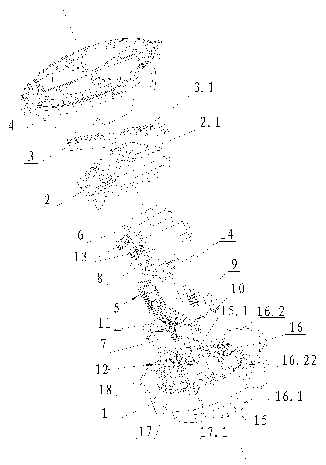
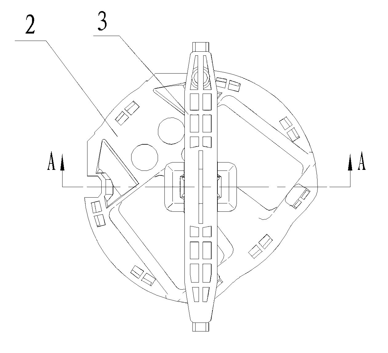
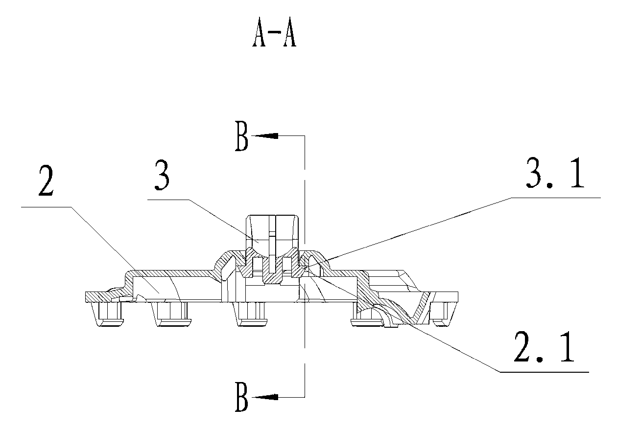
[0023] like figure 1 , figure 2 , image 3 , Figure 4 , Figure 5 , Image 6 and Figure 7 Shown a kind of automobile rearview mirror mirror driver, it comprises base 1, loam cake 2, floating bar 3, floating plate 4, transmission device 5 and two motors 6 that are connected with transmission device 5 and arc rack 7, so The base 1 is slidingly connected with the floating plate 4, the upper cover 2 is located between the base 1 and the floating plate 2 and is fixedly connected with the base 1, the transmission device 5, the motor 6 and the arc rack 7 are all located Between the upper cover 2 and the base 1, the floating rod 3 is located between the floating plate 4 and the upper cover 2, and the two ends of the floating rod 3 are rotatably connected with the floating plate 4, specifically the two ends of the floating rod 3 Ro...


PUM


Abstract

The invention discloses an automobile rearview mirror face actuator, comprising a base (1), an upper cover (2), a floating lever (3), a floating plate (4), a transmission device (5), and two motors (6) and arc racks (7) which are connected with the transmission device (5). The upper cover (2) is arranged between the base (1) and the floating plate (4) and is fixedly connected with the base (1); the transmission device (5), the motors (6) and the arc racks (7) are all arranged between the upper cover (2) and the base (1); the floating lever (3) is arranged between the floating plate (4) and the upper cover (2), and two ends of the floating lever (3) are rotatably connected with the floating plate (4); the middle part of the floating lever (3) is rotatably connected with the upper cover (2)in a buckled way; and the teeth of the arc racks (7) are all distributed on the outer arc surfaces of the arc racks. Compared with the prior art, the automobile rearview mirror face actuator has bigger bearing strength and the turning angle of the floating plate is bigger, so the mirror face can be adjusted in a bigger angle range and the safety can be better.

Description

technical field [0001] The invention relates to a mirror surface driver of an automobile rearview mirror. Background technique [0002] At present, the mirror driver of the automobile rearview mirror of the prior art comprises a base, an upper cover, a rack guide plate, a floating plate, a floating rod, a transmission device and two motors and an arc rack connected with the transmission device, and the base and the floating plate Sliding connection, the upper cover is located between the base and the floating plate, the upper cover and the base are fixedly connected, the transmission device, the motor and the curved rack are all located in the cavity formed by the upper cover and the base, and there is also a PCB board in the cavity And the rack guide plate, the floating rod is located between the floating plate and the upper cover, the two ends of the floating rod are rotatably connected with the floating plate, and the middle part of the floating rod is rotatably matched w...

Claims


Application Information

Patent Timeline
Patent Type & Authority Patents(China)
IPC IPC(8): B60R1/072
Inventor 周波傅家达
Owner NINGBO JINGCHENG CAR IND
Why Eureka
Try Eureka