Optical fiber drilling strain gauge

A strain gauge and optical fiber technology, applied in the field of optical fiber drilling strain gauges, can solve problems such as electromagnetic interference, lightning protection, zero drift, etc., and achieve the effect of reducing the zero drift problem

Inactive Publication Date: 2012-01-18
INST OF SEMICONDUCTORS - CHINESE ACAD OF SCI
View PDF6 Cites 7 Cited by
  • Summary
  • Abstract
  • Description
  • Claims
  • Application Information

AI Technical Summary

Problems solved by technology

[0007] In view of this, the main purpose of the present invention is to provide an optical fiber drilling strain gauge to solve the problems of electromagnetic interference, lightning protection and zero drift of existing drilling strain gauges

Method used


Image

  • Optical fiber drilling strain gauge
  • Optical fiber drilling strain gauge
  • Optical fiber drilling strain gauge

Examples


Embodiment Construction

[0024] In order to make the objectives, technical solutions and advantages of the present invention clearer, the present invention will be further described in detail below with reference to specific embodiments and accompanying drawings.

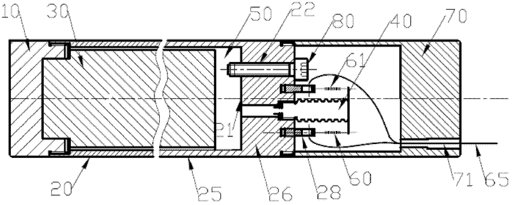
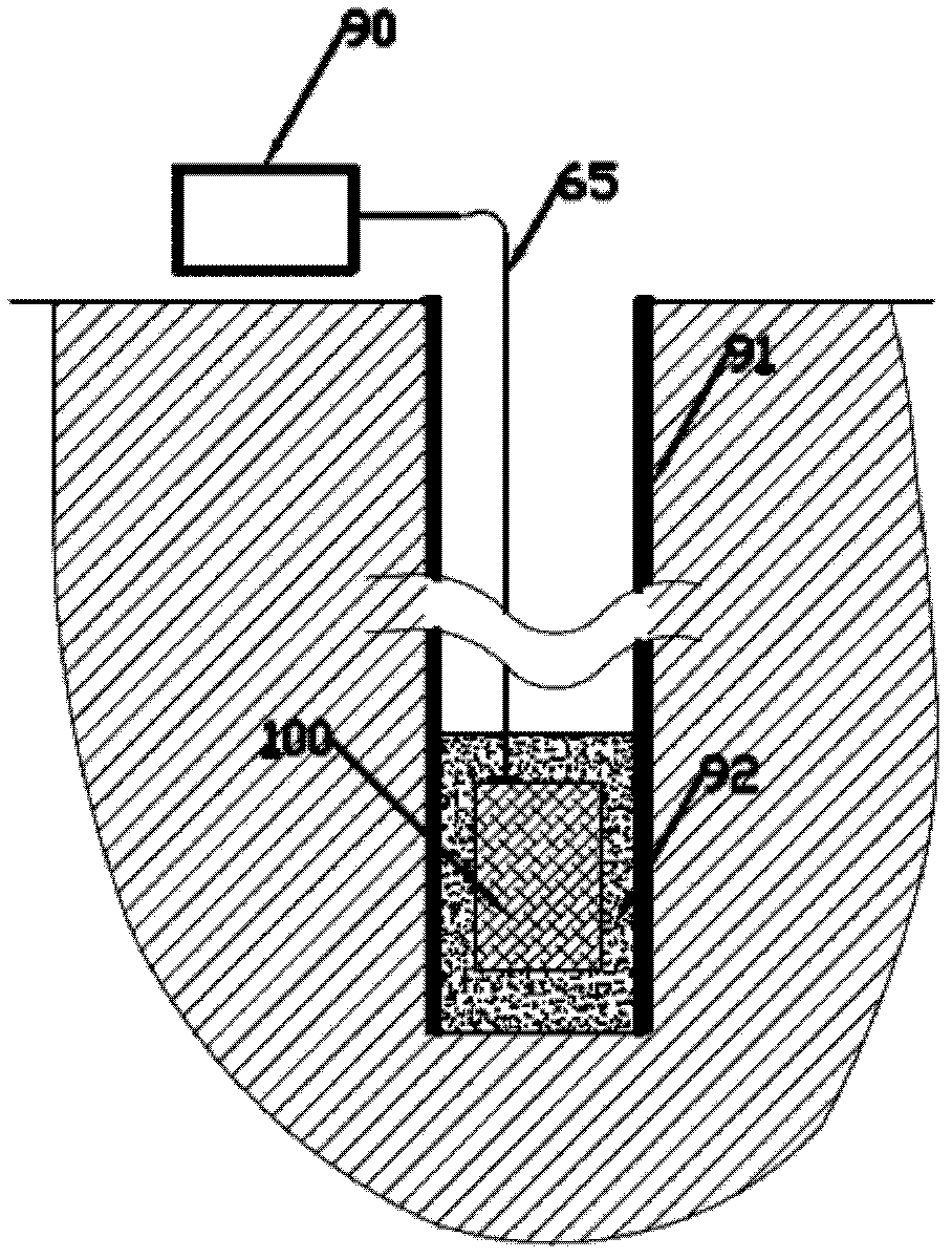
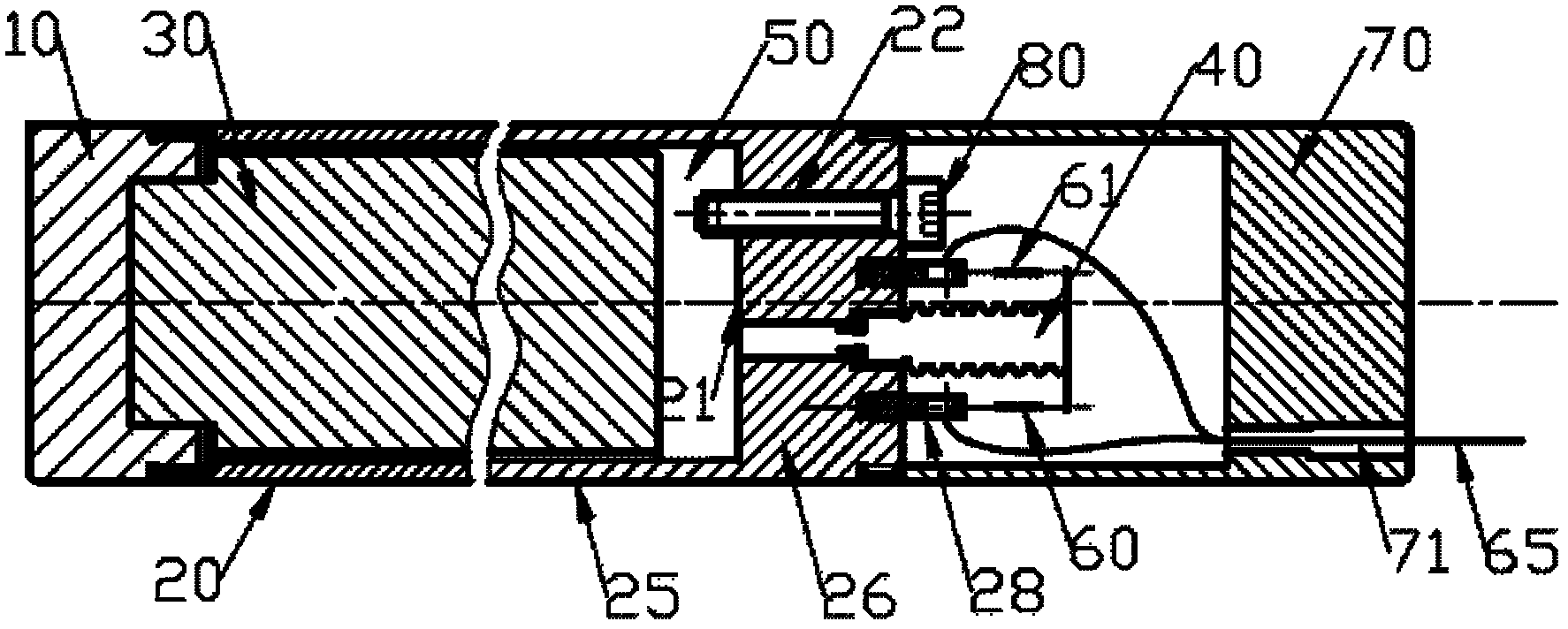
[0025] Please refer to Figure 1-Figure 2 , the optical fiber drilling strain gauge provided by the present invention includes: a strain tube 20 for sensing strain; a liquid 50 filled in the strain tube 20 for transmitting the strain felt by the strain tube 20; an end cap 10 for sealing; The bellows 40 at the bottom of the strain tube 20 is used to sense the pressure change in the strain tube 20; the bolts 80 installed at the bottom of the strain tube 20 are used for filling the liquid 50 and sealing; it is fixed to the end of the bellows 40 and the strain tube The measuring grating 60 at the bottom end 26 of the 20 is used to measure the end displacement of the bellows 40; the protective cover 70 installed at the bottom of the strain tube ...


PUM


Abstract

The invention discloses an optical fiber drilling strain gauge, which comprises a strain cylinder, liquid, an end cover, a corrugated pipe, a bolt, measurement gratings, a protective cover, an optical cable and ground demodulation equipment, wherein the strain cylinder is used for sensing strain; the liquid is filled in the strain cylinder and used for transferring the strain sensed by the strain cylinder; the end cover is used for sealing; the corrugated pipe is arranged at the bottom of the strain cylinder and used for sensing the change of pressure in the strain cylinder; the bolt is arranged at the bottom of the strain cylinder and used for filling liquid and sealing; the measurement gratings are fixed at the end of the corrugated pipe and the bottom of the strain cylinder and used for measuring the end displacement of the corrugated pipe; the protective cover is arranged at the bottom of the strain cylinder and used for protecting the internal structure of the optical fiber drilling strain gauge; the optical cable is connected with the optical fiber drilling strain gauge arranged at the bottom of a well and the ground demodulation equipment; and the ground demodulation equipment is used for demodulating the wavelength change of the measurement gratings so as to obtain a ground strain value. By using the optical fiber drilling strain gauge, the problems of electromagnetic interference, lightning stroke resistance and null shift of the conventional drilling strain gauge are solved.

Description

technical field [0001] The invention relates to the technical field of seismic detection, in particular to an optical fiber borehole strain gauge. Background technique [0002] The crust will deform under the action of the regional stress field, and the observation of borehole strain is an important means to study the crustal deformation and the change of the in-situ stress field. The borehole strain gauge can continuously record the crustal deformation before and after the earthquake and volcanic activity in minutes or even close to the sampling time of seismic measurement. Therefore, it plays an important role in earthquake prediction and geophysical research. [0003] Existing borehole strain gauges include volume strain gauges and component strain gauges (Qiu Zehua, et al., "Development Status of Borehole Strain Observation Abroad", Acta Seismological Journal, 2004). However, no matter which strain gauge is used, electrical sensors are used for detection. For example,...

Claims


Application Information

Patent Timeline
Patent Type & Authority Applications(China)
IPC IPC(8): G01B11/16
Inventor 张文涛李芳
Owner INST OF SEMICONDUCTORS - CHINESE ACAD OF SCI
Why Eureka
Try Eureka