Non-contact electrostatic intensity detection system

A technology of electrostatic strength and detection system, applied in electrostatic field measurement, measurement device, measurement of electrical variables, etc., can solve the problems of increasing cost, system complexity, zero drift of detection equipment, etc., to simplify the structure and conditioning circuit design, reduce The effect of small zero drift and cost reduction

Active Publication Date: 2020-11-03
WUXI GISSING AUTO ACOUSTIC PARTS TECH CO LTD
View PDF7 Cites 1 Cited by
  • Summary
  • Abstract
  • Description
  • Claims
  • Application Information

AI Technical Summary

Problems solved by technology

Among them, the cost of direct induction electrostatic detection is the lowest and the simplest, but the zero point drift of the detection equipment will be caused by the leakage of the induced charge; the rotary vane type and vibrating capacitive electrostatic detection equipment can be overcome to a certain extent by adding metal rotating blades and vibrating capacitive sensors. solves the problems existing in the direct induction electrostatic detection method, but these two electrostatic detection devices increase the cost and the complexity of the system

Method used


Image

  • Non-contact electrostatic intensity detection system
  • Non-contact electrostatic intensity detection system

Examples


Embodiment Construction

[0014] In order to facilitate the understanding of the present invention, the present invention will be described more fully below with reference to the associated drawings. Preferred embodiments of the invention are shown in the accompanying drawings. However, the present invention can be embodied in many different forms and is not limited to the embodiments described herein. On the contrary, the purpose of providing these embodiments is to make the disclosure of the present invention more thorough and comprehensive. It should be noted that when an element is considered to be "connected" to another element, it may be directly connected to the other element or there may be intervening elements at the same time. Unless otherwise defined, all technical and scientific terms used herein have the same meaning as commonly understood by one of ordinary skill in the technical field of the invention. The terms used herein in the description of the present invention are for the purpos...


PUM


Abstract

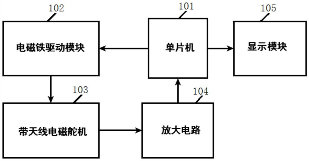
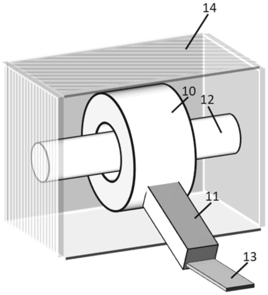
The invention discloses a non-contact electrostatic intensity detection system. The system comprises a single-chip microcomputer, an electromagnet driving module, an electromagnetic steering engine with an antenna, an amplifying circuit and a display module. The single-chip microcomputer is connected with the electromagnet driving module; the electromagnet driving module is connected with the electromagnetic steering engine with the antenna; the electromagnetic steering engine with the antenna is connected with the amplifying circuit; the display module is connected with the single-chip microcomputer. The single-chip microcomputer drives the electromagnetic steering engine with the antenna to swing up and down through the electromagnet driving module, an alternating-current sampling electrostatic field and inductive charges collected by the electromagnetic steering engine with the antenna are amplified through the amplifying circuit and then output to the single-chip microcomputer, andthe single-chip microcomputer calculates a relative electrostatic intensity value and outputs the relative electrostatic intensity value to the display module to be displayed. The antenna structure of the direct induction type electrostatic intensity detection system is improved, and zero drift is reduced; compared with a rotary vane type electrostatic detection system and a vibration capacitancetype electrostatic detection system, the structure of the induction antenna and the design of a conditioning circuit are greatly simplified, and the cost is reduced.

Description

technical field [0001] The invention relates to the technical field of electrostatic strength detection, in particular to a non-contact electrostatic strength detection system. Background technique [0002] At present, non-contact electrostatic strength detection equipment is mainly divided into three types: direct induction type, rotary vane type and vibration capacitance type. Among them, the cost of direct induction electrostatic detection is the lowest and the simplest, but the zero point drift of the detection equipment will be caused by the leakage of the induced charge; the rotary vane type and vibrating capacitive electrostatic detection equipment can be overcome to a certain extent by adding metal rotating blades and vibrating capacitive sensors. The problems existing in the direct induction electrostatic detection method are eliminated, but these two electrostatic detection devices increase the cost and the complexity of the system. The above problems need to be s...

Claims


Application Information

Patent Timeline
Patent Type & Authority Applications(China)
IPC IPC(8): G01R29/12G01R29/24
CPCG01R29/12G01R29/24
Inventor 赵嘉鹏黄威阮海林李龙晨陈晓君朱可达
Owner WUXI GISSING AUTO ACOUSTIC PARTS TECH CO LTD
Why Eureka
Try Eureka