Non-polar two-line system communication circuit

A communication circuit, two-wire technology, applied in the fixed station through two conductor transmission systems and other directions, can solve the problems of wiring errors, damage to master and slave components, and high costs, and achieve the effect of reducing requirements.

Active Publication Date: 2012-01-18
SHENZHEN MCQUAY AIR CONDITIONING
5 Cites 32 Cited by

AI-Extracted Technical Summary

Problems solved by technology

like figure 1 As shown, in the traditional four-wire communication connection mode, the master end of the air conditioner and the slave end of the air conditioner use two communication lines for communication between the master end and the s...

Method used

[0020] The present invention loads the communication signal onto the power line to realize simultaneous...

Abstract

The invention discloses a non-polar two-line system communication circuit which aims to solve the technical problem of preventing the occurrence of errors in the process of connection. The invention adopts the following technical scheme: a non-polar two-line system communication circuit comprises a host terminal and a slave terminal, wherein the host terminal is connected with the slave terminal and controls the slave terminal, the inside of the host terminal is provided with a host-terminal sending and receiving line module, the inside of the slave terminal is provided with a slave-terminal sending and receiving line module, and the host-terminal sending and receiving line module is connected with the slave-terminal sending and receiving line module in a non-polar two-line system connection mode. Compared with the prior art, an indoor unit controller for air conditioners supplies power for a temperature control device for air conditioners and carries out communication with the temperature control device by a power line, and the connection mode is a non-polar connection mode; and two lines can simultaneously carry out power supply and communication, thereby solving the problem that two lines simultaneously supply power and transmit signals, and reducing the demands on leads and installation.

Application Domain

Fixed station two-conductor transmission systems

Technology Topic

Image

  • Non-polar two-line system communication circuit
  • Non-polar two-line system communication circuit
  • Non-polar two-line system communication circuit

Examples

  • Experimental program(1)

Example Embodiment

[0013] The technical solution of the present invention will be further described in detail below in conjunction with the accompanying drawings and embodiments.
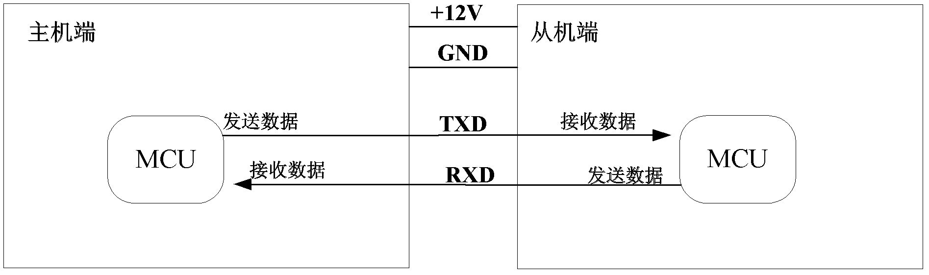
[0014] like figure 1 As shown, in air-conditioning equipment or other household appliances in the prior art, a four-wire transmission method is used for communication between the master end and the slave end, that is, the TXD pins and RXD pins of the microprocessors at the master and slave end are connected to each other. , the two power lines on the host end, together with the signal line, are drawn out from the terminal block, and serve as power supply lines for the slave end, so that the host end supplies power to the slave end. The master end may be an air conditioner indoor unit controller, and the slave end may be a thermostat of the air conditioner.
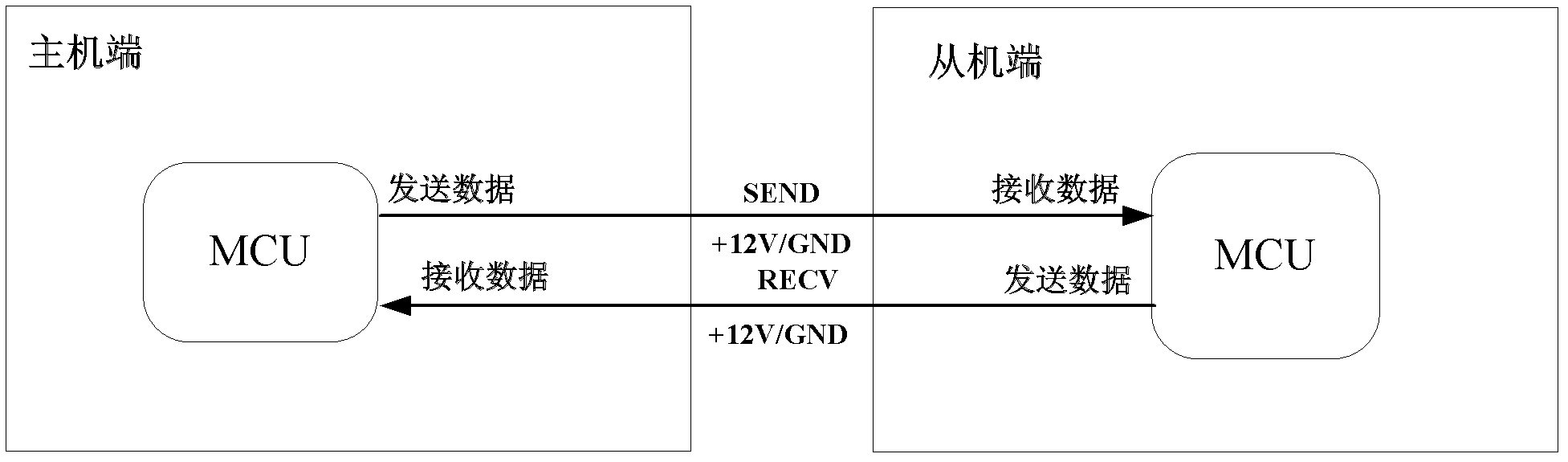
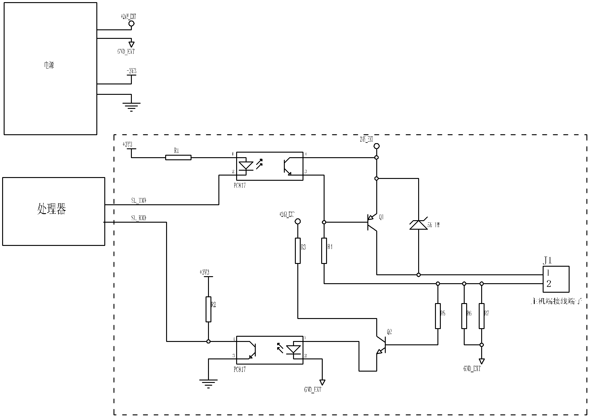
[0015] like figure 2 As shown, the non-polar two-wire communication circuit of the present invention has a master end and a slave end, the master end is provided with a master end sending and receiving line module, and the slave end is provided with a slave end sending and receiving line Module, the sending and receiving line module of the master end is connected with the sending and receiving line module of the slave end using a non-polar two-wire wiring method.
[0016] like image 3 As shown, the sending and receiving circuit module of the host end adopts an 8-bit microprocessor of the prior art, and one end of the signal sending pin SL_TXD is connected with the controller in the host end, and the other end is connected with 2 pins of the first optocoupler PC817 , pin 1 is connected to the +3V3 voltage pin through the first resistor R1, the +3V3 voltage pin is the 3.3V power supply pin of the host computer, which supplies power for the microprocessor, and the 4 pins are respectively connected to the +24V_EXT voltage pin, the +24V_EXT and GND_EXT are the host The 24V extended power supply drawn from the terminal is used to supply power to the slave terminal. In order to ensure system reliability, the 24V power supply and the 3.3V power supply of the host terminal need to be isolated. The cathode of the diode, the 3 pins are divided into two ways, one is connected to the base of the first triode Q1, and the other is connected to the 2 pins of the first wire controller terminal J1 through the fourth resistor R4; the set of the first triode Q1 The electrode and the anode of the first Zener diode are connected to pin 1 of the first wire controller terminal J1; the output end of the fourth resistor R4 is also connected to the base of the second triode Q2 through the fifth resistor R5; The six resistors R6 are connected to the GND_EXT pin; the seventh resistor R7 is connected to the GND_EXT pin; the collector of the second transistor Q2 is connected to the +24V_EXT voltage pin through the third resistor R3, and the emitter of the second transistor Q2 is connected to the second photocoupler Pin 1 of the device, pin 2 is connected to GND_EXT pin, pin 3 is grounded, pin 4 is divided into two circuits, one is connected to +3V3 voltage pin through the second resistor R2; the other is connected to SL_RXD pin.
[0017] like Figure 4 As shown, the sending and receiving line module of the slave machine adopts an 8-bit microprocessor of the prior art, and pins 1 and 2 of the second wire controller terminal J2 are connected to the sending and receiving line circuit of the host side through an extension line. Pin 1 and pin 2 of the first wire controller terminal J1 adopt non-polarity connection, and pin 1 and pin 2 of the second wire controller terminal J2 of the rectifier circuit of the sending and receiving line module of the slave end are connected to the first diode D1, the second diode D2, the third diode D3 and the fourth diode D4 are connected in parallel, and the second wire controller terminal J2 is respectively connected to the anode of the first diode D1 and the anode of the third diode D3 Cathode, the cathode of the first diode D1 is connected to the cathode of the second diode D2, the cathode of the second diode D2 is connected to pin 2 of the second wire controller terminal J2, and the anode of the third diode D3 is connected to the fourth The anode of the diode D4, the cathode of the fourth diode D4 are connected to pin 2 of the second wire controller terminal J2, and the cathode of the first diode D1 is respectively connected to one end of the first capacitor C1, one end of the second capacitor C2, The pins 1 and 3 of the regulator 78L05 are connected to one end of the third capacitor C3 and the fourth capacitor C4, and the other ends of the third capacitor C3 and the fourth capacitor C4 are grounded and connected to the anode of the fourth diode D4, Pin 2 of the regulator 78L05 is connected to the anode of the fourth diode D4, the other end of the third capacitor C3 and the fourth capacitor C4, and the ground, and the other end of the second capacitor C2 is connected to the anode of the fourth diode D4. A capacitor C1 is connected to the anode of the fourth diode D4, and the fourth diode D4 is grounded; the cathode of the first diode D1 is respectively connected to the collector of the fifth triode Q5 through the thirteenth resistor R13 Connect the tenth resistor R10 through the 18V voltage stabilizing diode; the base of the fifth transistor Q5 is connected to the collector of the sixth transistor Q6 through the fourteenth resistor R14, and connect the collector of the sixth transistor Q6 through the fourteenth resistor R14 and the twentieth resistor R14. The seven resistors R27 are connected to the +5V voltage pin, the base of the sixth triode Q6 is connected to the TX pin of the microprocessor through the twenty-eighth resistor R28, and the emitter is grounded and connected to the emitter of the fifth triode Q5; the tenth Resistor R10 is respectively connected to the base of the third transistor Q3 via the twenty-ninth resistor R29, grounded and connected to the emitter of the fifth transistor Q5 through the ninth resistor R9; the collector of the third transistor Q3 is respectively connected to The fifteenth resistor R15 is connected to the +5V voltage pin, and the base of the fourth transistor Q4 is connected through the eleventh resistor R11; the emitter of the third transistor Q3 is respectively connected to the ninth resistor R9 and the fifth transistor Q5. Emitter and ground; the emitter of the fourth triode Q4 is respectively connected to the emitter of the third triode Q3, the ninth resistor R9, the fifth triode Q5 and ground; the collector is connected to the RX pin of the microprocessor, Connect to the +5V voltage pin through the twelfth resistor R12.
[0018]The sending pin SL_TXD pin of the host side sends and receives the signal of the line module to couple the signal to the base of the first triode Q1 through the optocoupler, so as to control the conduction from the collector to the emitter of the first triode Q1 and cut-off; when the SL_TXD pin signal is high level, the emitter of the first triode Q1 is turned on, and the potential of pin 1 of the first wire controller terminal J1 is 24V; when the SL_TXD pin signal is low level, the first three The emitter of the pole tube Q1 is cut off, and the potential of pin 1 of the output terminal J1 is 24-5=19V. The sending and receiving line module of the slave side takes out the actual signal by judging the difference between the level 24V and 19V. J1 is connected to the second wire control terminal J2 of the sending and receiving line module of the slave side through the extension line, and supplies power to the slave side after passing through the rectification bridge and filtering; Convert and reverse the polarity, take out the signal and send it to the receiving pin of the microprocessor, so as to completely restore the signal; the TX pin of the sending end of the slave side sending and receiving line module, when the sending signal is low, the fifth triode Q5 conducts On, the thirteenth resistor R13 increases the load current; otherwise, the sending signal is high, the fifth triode Q5 is turned off, and the load current decreases. The two current states reflect the change of the high and low levels of the sending pin. This transmission mode is Current signal transmission; the receiving pin of the sending and receiving line module on the host side is the SL_RXD pin, and the process of sending and receiving line modules on the slave side will lead to changes in current, which will cause voltage changes in the sixth resistor R6 and the seventh resistor R7 of the sampling resistor , driving the second triode Q2 to be turned on and off, and the signal is sent to the SL_RXD pin through the second optocoupler, that is, to the receiving pin of the microprocessor on the host side.
[0019] The signal transmission adopts a half-duplex mode, connected to an ordinary optocoupler, and the signal baud rate can support up to 4800bps. If it is replaced with a high-speed optocoupler, the signal baud rate can reach 19200bps.
[0020] The invention loads the communication signal to the power line, realizes simultaneous power supply and communication, and has the advantages of low installation requirements and low cost.

PUM

no PUM

Description & Claims & Application Information

We can also present the details of the Description, Claims and Application information to help users get a comprehensive understanding of the technical details of the patent, such as background art, summary of invention, brief description of drawings, description of embodiments, and other original content. On the other hand, users can also determine the specific scope of protection of the technology through the list of claims; as well as understand the changes in the life cycle of the technology with the presentation of the patent timeline. Login to view more.

Similar technology patents

General wiper connecting apparatus

Owner:DANYANG UPC AUTO PARTS

Method, system and device for sharing enterprise address book

InactiveCN102087723AReduce processing overheadLower requirementResourcesAddress bookTree structure
Owner:CHINA MOBILE COMM GRP CO LTD

Classification and recommendation of technical efficacy words

Why Eureka
Try Eureka