Bridge

A technology of bridges and I-beams, applied in bridges, bridge parts, bridge construction, etc., can solve problems affecting bridge fatigue performance, bridge structure fatigue damage, negative impact on bridge safety, etc.

Inactive Publication Date: 2012-01-25
CHINA SHENHUA ENERGY CO LTD +3
View PDF6 Cites 14 Cited by
  • Summary
  • Abstract
  • Description
  • Claims
  • Application Information

AI Technical Summary

Problems solved by technology

[0003] At present, with the increasing number of means of transportation, roads and railways have begun to develop from the ground to the air, forming an increasing number of road bridge projects, but there are many problems in today's road bridge structures: the design load of the bridge is "medium-live load". If the load factor is too large, the safety reserve of the bridge will be greatly reduced, and long-term operation will have a greater negative impact on the safety of the bridge; under the long-term load of trains and large passenger and freight vehicles, the fatigue damage of the bridge structure will be aggravated, and the safety reserve of the bridge will be greatly reduced ; When a vehicle passes a bridge at a certain speed, it will produce a vertical dynamic effect, and the dynamic coefficient is generally used (the ratio of the maximum response value of the bridge due to the vertical action of the vehicle passing through to the maximum response value of the vertical action of the vehicle when it is stationary) The main factors affecting the dynamic coefficient are the form and span length of the bridge structure, the type of rolling stock, the equipment status of the bridge line, etc.; under the long-term load of trains and large passenger and freight vehicles, the fatigue damage of the bridge structure will be aggravated. Affect the fatigue performance of the bridge and shorten the fatigue life of the structure, so it is urgent to study a new type of composite bridge

Method used


Image

  • Bridge
  • Bridge
  • Bridge

Examples


Embodiment Construction

[0061]Specific embodiments of the present invention will be described in detail below in conjunction with the accompanying drawings. It should be understood that the specific embodiments described here are only used to illustrate and explain the present invention, and are not intended to limit the present invention.

[0062] In the present invention, unless stated otherwise, the used orientation words such as "up and down" usually refer to the directions shown in the drawings. "Longitudinal" refers to the length direction of the bridge, "transverse" refers to the width direction of the bridge, and "outside" mentioned in the specification refers to both sides along the transverse direction of the bridge.

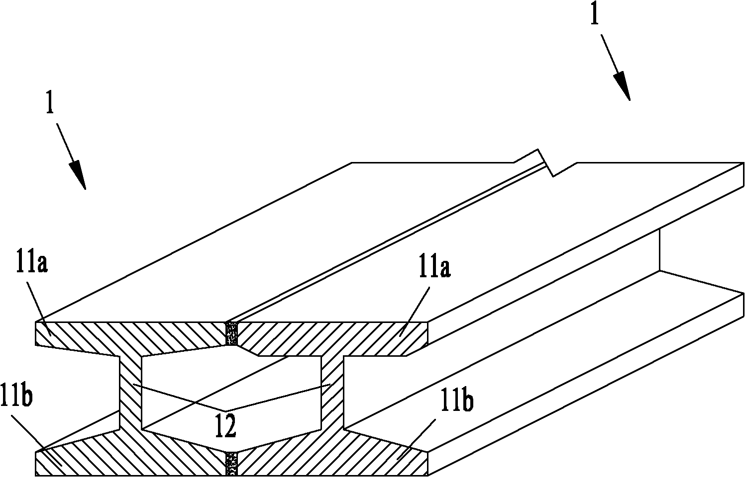
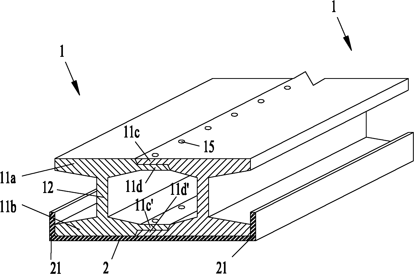
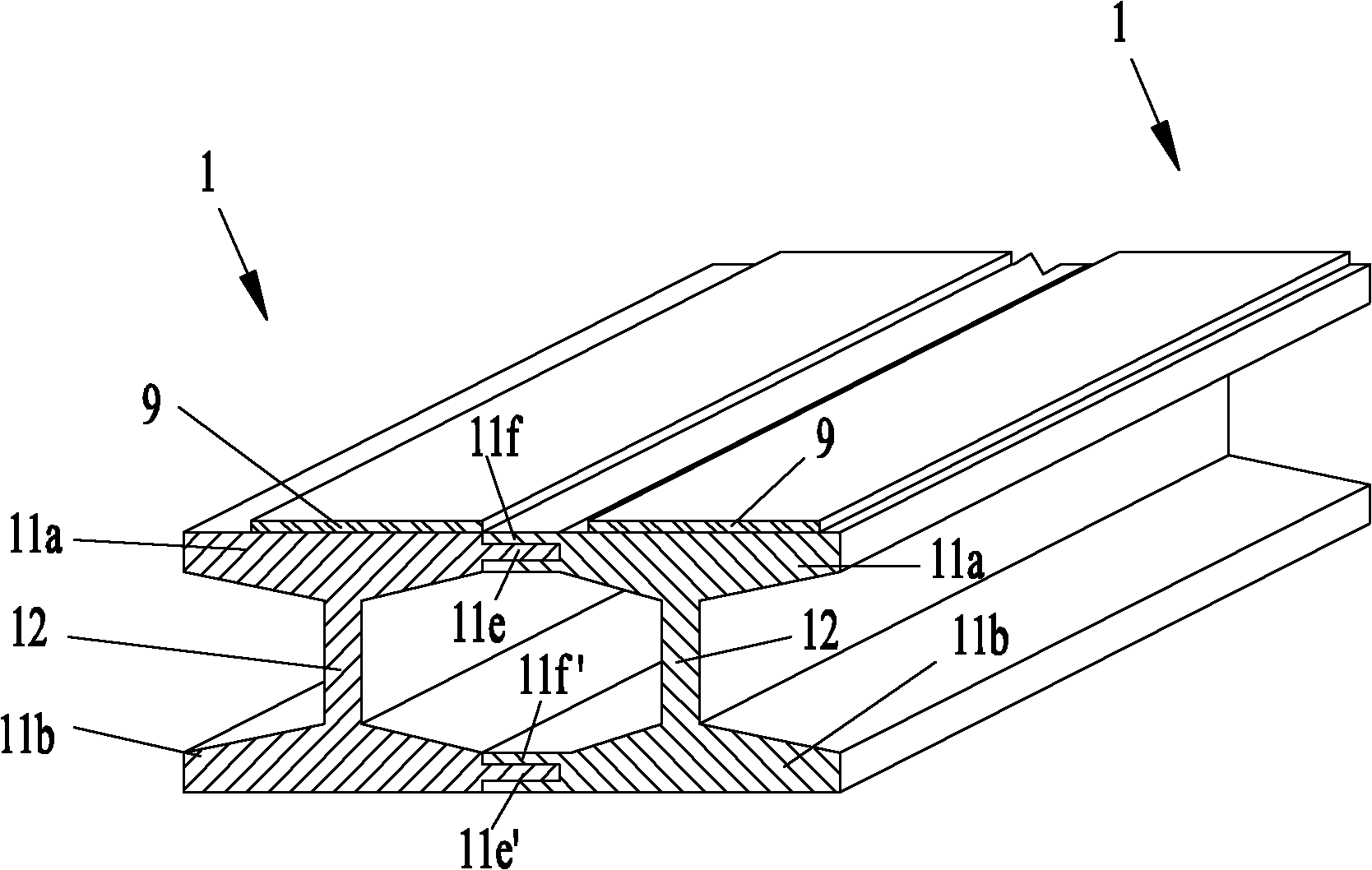
[0063] like Figures 1 to 19 As shown in , the present invention provides a bridge comprising an I-beam 1 comprising an upper flange 11a, a lower flange 11b and a web supported between the upper flange 11a and the lower flange 11b. Plate 12, wherein there are multiple I-bea...


PUM


Abstract

The invention discloses a bridge which comprises I-shaped beams (1), wherein each I-shaped beam (1) comprises a top flange (1a), a bottom flange (1b) and a web (12) supported between the top flange (1a) and the bottom flange (1b), wherein the I-shaped beams (1) are multiple and are arranged side by side, and two adjacent I-shaped beams (1) are connected mutually. Through connecting two I-shaped beams (1) mutually, the stability of integral bridge can be improved, and the vertical rigidity of the bridge is improved.

Description

technical field [0001] The present invention relates to the construction field, and more specifically, to a bridge. Background technique [0002] A bridge is a structure built for roads to cross natural or man-made obstacles, for example, bridges across rivers and ravines. Typically, a bridge includes a girder and piers supporting the girder. According to different purposes, bridges can be divided into road bridges and railway bridges. [0003] At present, with the increasing number of means of transportation, roads and railways have begun to develop from the ground to the air, forming an increasing number of road bridge projects, but there are many problems in today's road bridge structures: the design load of the bridge is "medium-live load". If the load factor is too large, the safety reserve of the bridge will be greatly reduced, and long-term operation will have a greater negative impact on the safety of the bridge; under the long-term load of trains and large passeng...

Claims


Application Information

Patent Timeline
Patent Type & Authority Applications(China)
IPC IPC(8): E01D2/00E01D2/02E01D19/00
Inventor 余志武薛继连贾晋中宋力李进洲李晓建
Owner CHINA SHENHUA ENERGY CO LTD
Why Eureka
Try Eureka