Transition structure for preventing and treating bump at bridge-head and construction method thereof

A transitional structure, bridge head jumping technology, applied in the direction of bridges, bridge parts, bridge construction, etc., can solve the problems of not completely solving the bridge head jumping, not giving a clear design method, etc., to reduce the head end bridge head jumping after the platform. , The effect of avoiding bridge jumping and convenient construction

Pending Publication Date: 2019-06-07
SHENYANG JIANZHU UNIVERSITY
View PDF0 Cites 7 Cited by
  • Summary
  • Abstract
  • Description
  • Claims
  • Application Information

AI Technical Summary

Problems solved by technology

Although this point of view and method will reduce the differential settlement and alleviate the bridge head jumping, it does not give a clear and specific design method, but generally suggests that the bridge head jumping should be regarded as an independent design problem, and the prevention of its occurrence should be taken as the design goal one
In addition, many experts and scholars in China have put forward the design method of increasing the structure of the bridge head slab structure, the pre-throwing method, and the special treatment of the bridge head roadbed, etc., which cannot completely solve the problem of bridge head jumping, and need to be used together with other treatment measures.

Method used


Image

  • Transition structure for preventing and treating bump at bridge-head and construction method thereof
  • Transition structure for preventing and treating bump at bridge-head and construction method thereof
  • Transition structure for preventing and treating bump at bridge-head and construction method thereof

Examples


Embodiment Construction

[0037] It should be noted that all directional indications (such as up, down, left, right, front, back...) in the embodiments of the present invention are only used to explain the relationship between the components in a certain posture (as shown in the accompanying drawings). Relative positional relationship, movement conditions, etc., if the specific posture changes, the directional indication also changes accordingly.

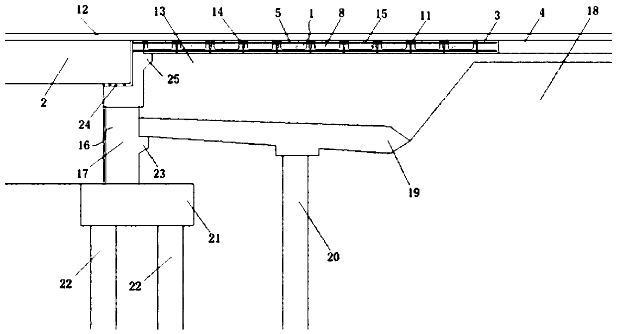
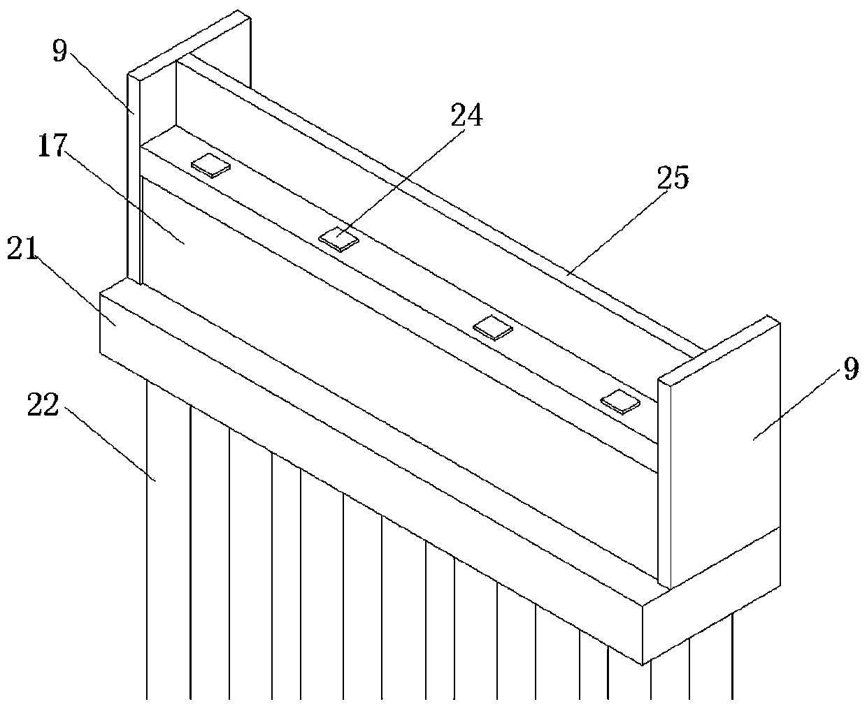
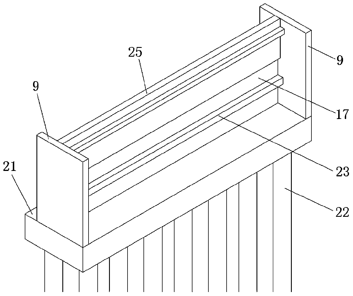
[0038] Such as Figure 1 to Figure 7 Shown, the present invention provides a kind of transitional structure and its construction method of prevention bridge head jumping:

[0039]A transitional structure for preventing vehicle jumping at the bridge head, including a beam body 2, which is the structural main body of the bridge, and extends at both ends, and is characterized in that: the fixed installation bridge abutment 16 at both ends of the beam body 2 is integrally formed structure, the beam body 2 is loaded and limited, and the joint board member 1 is c...


PUM


Abstract

The invention provides a transition structure for preventing and treating bump at bridge-head and a construction method thereof. The structure of the transition structure for preventing and treating the bump at the bridge-head comprises a beam body; bridge abutments are fixedly mounted at the two ends of the beam body; one ends of towing plates are fixedly mounted at the middle parts of the bridgeabutments; the other ends of towing plates are buried in a subgrade; the parts behind the bridge abutments and the upper parts of the towing plates are filled with backfilled earth; combined approachslab members are laid on the upper surface of the backfilled earth; and one ends of the combined approach slab members are fixedly mounted on the external sides of the upper ends of the bridge abutments. The construction method comprises the steps of erecting the bridge abutments molded with brackets, constructing the towing plates on the brackets to form two layers of backfill structures, and arranging the combined approach slab members to improve a bearing structure; and therefore, road surface roughness and breakage at the bridge head connecting part caused by uneven settlement of the backfilled earth in the using process are reduced to realize an effect of preventing and treating the bump at the bridge-head; and meanwhile, through the structure combination, energy saving and environmentally friendly properties are realized, the construction period is shortened, template members are saved, and accuracy and quality are very well guaranteed.

Description

technical field [0001] The invention belongs to the technical field of prevention and control of vehicle jumping at the bridge head of roads and bridges, and in particular relates to a transition structure for preventing vehicle jumping at the bridge head and a construction method thereof. Background technique [0002] Bridge head jumping refers to the phenomenon that the wheels vibrate up and down when the car passes through the road section due to the settlement between the bridge culvert structure and the embankment behind the bridge culvert platform exceeding a certain limit value, and this settlement phenomenon will affect the normal operation of high-grade highways. Use and people's overall evaluation of high-grade highways, while the up and down vibration of the wheels will also affect driving safety, speed, comfort and the service life of cars and bridges. [0003] Bridge head jumping is caused by the difference in settlement between the rigidly supported abutment an...

Claims


Application Information

Patent Timeline
Patent Type & Authority Applications(China)
IPC IPC(8): E01D19/12E01C5/06E01C3/04
Inventor 宋福春赵洁霍省伟任婧杨柄楠浮涛袁良东陈贤
Owner SHENYANG JIANZHU UNIVERSITY
Why Eureka
Try Eureka