
Test device with controllable vibrational degrees of freedom for vortex-induced vibration of cylinders

A technology of vortex-induced vibration and testing equipment, which is applied in vibration testing, measuring equipment, testing of machine/structural components, etc., and can solve problems such as inability to reveal the influence of fluid-solid coupling characteristics, inapplicability, and impossibility of experimental research

Inactive Publication Date: 2012-01-25
OCEAN UNIV OF CHINA
View PDF2 Cites 19 Cited by
  • Summary
  • Abstract
  • Description
  • Claims
  • Application Information

AI Technical Summary

Problems solved by technology

[0016] a) The vortex-induced vibration test that can independently control the unidirectional vibration cannot be carried out. Therefore, it cannot be used for the experimental research on the influence of the flow-wise (lateral) vibration of the elastic cylinder on the transverse (flow-wise) vortex-induced vibration, and cannot reveal the flow direction of the elastic cylinder. The essential characteristics of (transverse) fluid-solid coupling effects on vortex discharge, vortex-induced lift and drag forces cannot reveal the fluid-solid coupling characteristics of flow-direction and transverse coupled vibrations and their influence on vortex-induced vibrations
[0017] b) The fluid-solid coupling characteristics of large displacement vortex-induced vibration of deep water risers cannot be simulated. Large displacement means geometric nonlinearity, and the linear small displacement assumption is no longer applicable. Therefore, the traditional vortex-induced vibration test device is not suitable for strong geometric nonlinearity. Research on vortex-induced vibration of deepwater riser

Method used


Image

  • Test device with controllable vibrational degrees of freedom for vortex-induced vibration of cylinders
  • Test device with controllable vibrational degrees of freedom for vortex-induced vibration of cylinders
  • Test device with controllable vibrational degrees of freedom for vortex-induced vibration of cylinders

Examples


Embodiment Construction

[0032] The present invention will be described in detail below in conjunction with the accompanying drawings and specific embodiments.

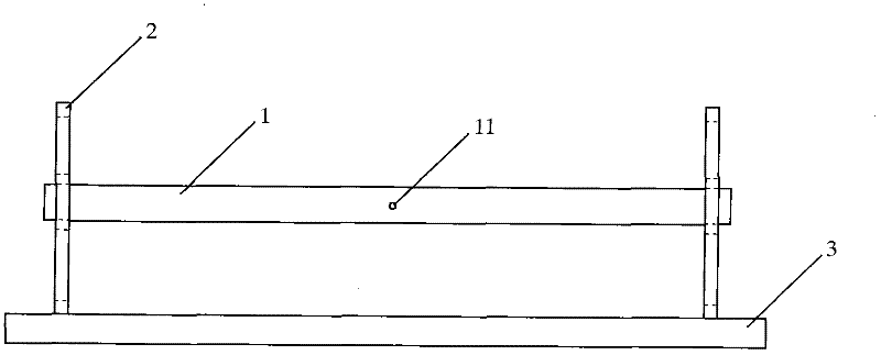
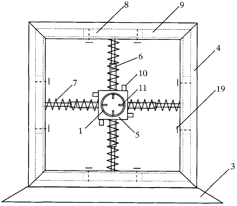
[0033] The vortex-induced vibration of the cylinder includes the vibration of two degrees of freedom in the direction of flow and in the transverse direction. The mutual influence of vibration, to study the fluid-solid coupling effect of flow-direction and transverse vortex-induced vibration and its influence on vortex-induced vibration, the test device should be able to control the flow-direction or lateral vibration respectively, that is, constrain the flow-direction or lateral vibration, so that the test model Only for lateral or downstream vibration.

[0034] Since the vortex-induced vibration of the cylinder includes vibration of two degrees of freedom, the single-degree-of-freedom vibration test is used to study the characteristics of the vortex-induced vibration of the cylinder under the condition that the vibration of the other degree...


PUM

PropertyMeasurementUnit
Lengthaaaaaaaaaa

Abstract

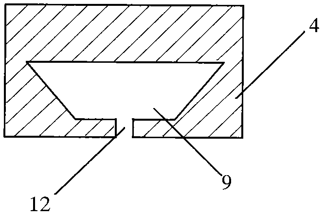
The invention relates to a test device for research on vibration of construction in a flow field, and specifically to a test device with controllable vibrational degrees of freedom for vortex-induced vibration of cylinders. The test device comprises elastic supports arranged on a pedestal and a model pipeline arranged on the elastic supports, wherein, the elastic support comprises a rack and a pipe clamp for installing the model pipeline, a spring core bar is provided between the rack and the pipe clamp, a spring is sleeved on the spring core bar, chutes are provided on the rack, slide blocks are provided in the chutes, and the slide blocks are connected with the pipe clamp through the spring core bar. According to the invention, vibration at two directions can be controlled respectively, which enables the problem that fluid-solid coupling can not be tested in research on vortex-induced vibration to be overcome.

Description

technical field [0001] The invention relates to a test device for studying the vibration of a structure in a flow field, in particular to a cylindrical vortex-induced vibration test device with controllable vibration degrees of freedom. Background technique [0002] Vortex-induced vibration is a special vibration form of a cylinder in the flow field, and it is the vibration caused by the vortex shedding at the wake of the cylinder. The research on vortex-induced vibration has a history of more than 60 years, but in recent years, the riser vortex-induced vibration problem caused by the development of deep-water oil and gas in the ocean has set off a new round of cylinder vortex-induced vibration research upsurge. [0003] The study found that the traditional vortex-induced vibration theory cannot well explain the special vortex-induced vibration phenomenon of deepwater risers, such as large vibration amplitude. The traditional vortex-induced vibration theory holds that the r...

Claims


Application Information

Patent Timeline
IPC IPC(8): G01M7/06G01M7/02
Inventor 黄维平孟庆飞顾恩凯魏东泽丁曼
Owner OCEAN UNIV OF CHINA
Learn More