Paper feeder and image forming device using same

A paper feeding and paper technology, applied in the field of paper feeders, can solve problems such as paper skew, movement or wrinkling, and image quality degradation

Inactive Publication Date: 2012-02-01
RICOH KK
View PDF4 Cites 22 Cited by
  • Summary
  • Abstract
  • Description
  • Claims
  • Application Information

AI Technical Summary

Problems solved by technology

[0004] That is to say, in the prior art, due to the meshing structure between the racks, the sheets stacked on the base may be skewed, shifted, or wrinkled in the width direction, thereby deteriorating the quality of image formation.

Method used


Image

  • Paper feeder and image forming device using same
  • Paper feeder and image forming device using same
  • Paper feeder and image forming device using same

Examples


no. 1 example

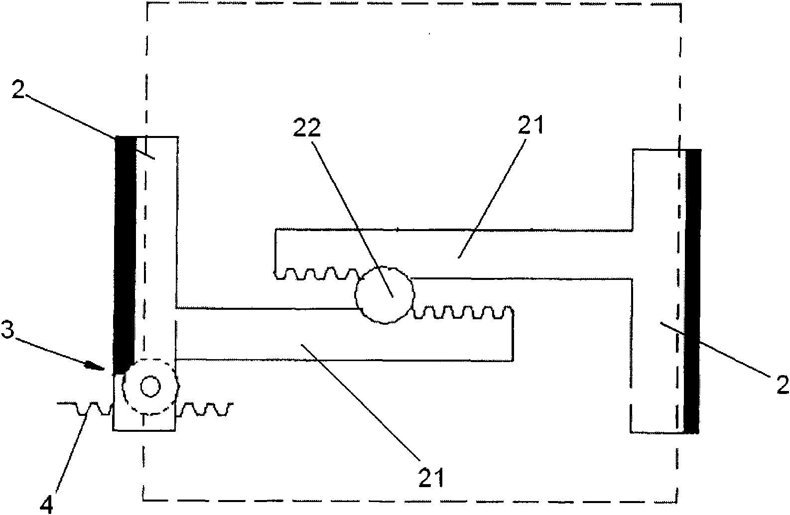
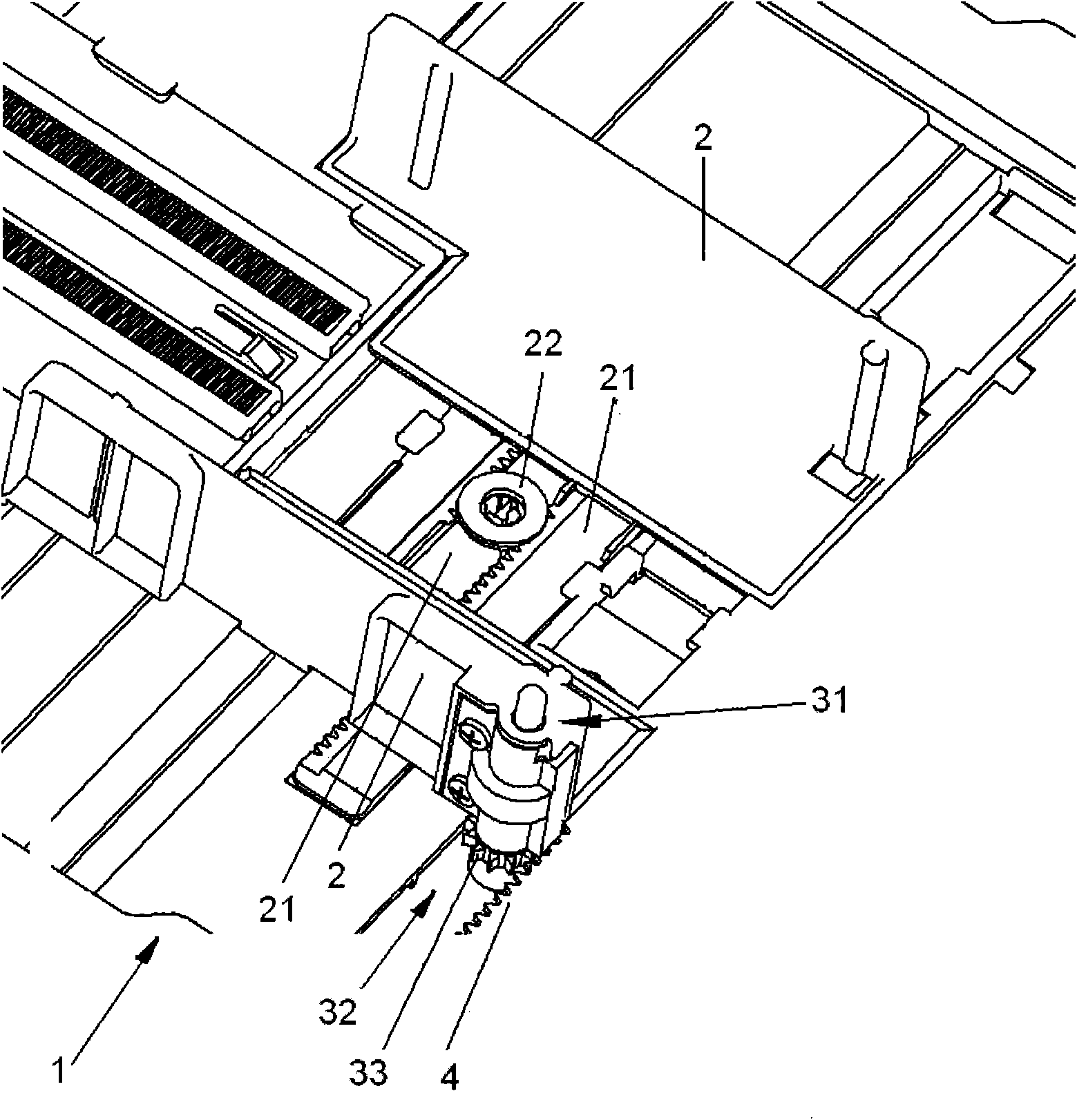
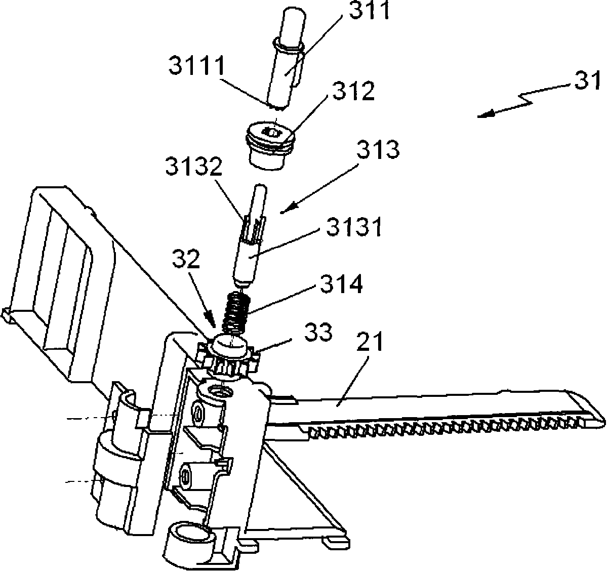
[0023] Such as Figures 1 to 3 As shown, the paper feeder of the present invention includes a base 1 for stacking paper. Two side baffles 2 arranged on the base 1, the two side baffles 2 on the paper (such as figure 1 Indicated by the dotted line in ) in the width direction (such as figure 1 The side fences 2 face each other in the left-right direction), and the two side fences 2 can move closer to or farther away from each other along the width direction of the paper. Specifically, as figure 1 and 2 As shown, two side fences 2 are respectively provided with a rack 21 extending along the paper width direction, and the two racks 21 are both engaged with the central gear 22 provided on the base 1 . When one side baffle 2 in the two side baffles 2 is pushed / pulled to move, the other side baffle 2 is driven to move through the meshing action between the rack 21 and the sun gear 22, so that the two side baffles The side fences 2 can simultaneously approach or move away from ea...

no. 2 example

[0037] The following will refer to the attached Figure 4 The second embodiment of the present invention is described, and the structures similar to those of the first embodiment in the second embodiment are given the same or similar numbers, and their explanations are omitted. Only the differences between the second embodiment and the first embodiment will be explained below.

[0038] Such as Figure 4 As shown, the difference between the second embodiment of the present invention and the first embodiment lies in the specific structure of the rotation adjustable part. In the second embodiment of the present invention, the rotation adjustable part 52 is a spring coil clutch, and the spring coil clutch includes: an input shaft 521 , an output shaft 522 , a spring 523 and a sleeve 524 . The output shaft 522 and the input shaft 521 are connected to each other by snap fit, so that the output shaft 522 and the input shaft 521 can rotate relatively. The sleeve 524 fits on the spr...


PUM


Abstract

The invention provides a paper feeder and an image forming device using the same. The paper feeder comprises a base, two side baffle plates arranged on the base and a width adjusting member, wherein the width adjusting member comprises an adjustable locking component and a fixed rack arranged on the base; the adjustable locking component comprises a control part, a rotary adjustable part and a gear, wherein the gear is engaged with the fixed rack; when the rotary adjustable part is controlled by the control part, the gear is in a second state of rotating in only one direction; and when the rotary adjustable part is not controlled by the control part, the gear is in a first state of rotating in two mutually opposite directions. Through the structure, locking of the two side baffle plates is realized when the two side baffle plates are continuously adjusted, so that gaps are not formed between the two sides of a piece of paper in the width direction and the side baffle plates, and the image forming quality is ensured. The invention also provides the image forming device provided with the paper feeder.

Description

technical field [0001] The present invention relates to a sheet feeder, and more particularly, to a sheet feeder for an image forming apparatus and an image forming apparatus using the same. Background technique [0002] In the prior art, a paper feeder in an image forming device generally includes a base on which paper is carried, and two side fences arranged on the base and capable of approaching and moving away from each other, the two side fences are adjusted to Adapt to the width of the paper placed on the base, so as to ensure that the paper placed on the base will not be skewed or moved in the width direction. In the traditional paper feeder, when one of the two side fences is provided with a snap-in rack with multiple teeth, the snap-in rack is engaged with the corresponding fixed rack on the base to realize Locking and unlocking of the two side fences. [0003] However, in the prior art, especially in the image forming field, the above-mentioned fixed racks and en...

Claims


Application Information

Patent Timeline
Patent Type & Authority Applications(China)
IPC IPC(8): B65H1/04
Inventor 吴定强邓辉照
Owner RICOH KK
Why Eureka
Try Eureka