Valve drive device

一种阀驱动、阀座的技术,应用在阀装置、阀的操作/释放装置、多通阀等方向,能够解决耗费成本、表面硬度低、高精度的面歪斜等问题,达到抑制制造成本、高面精度、制造成本的增大抑制的效果

Active Publication Date: 2006-03-29
SANKYO SEIKI MFG CO LTD
View PDF0 Cites 7 Cited by
  • Summary
  • Abstract
  • Description
  • Claims
  • Application Information

AI Technical Summary

Problems solved by technology

[0005] Therefore, in the prior art, when manufacturing the valve seat plate 13 ′, it is necessary to cut (lathe) thick SUS, so there is a problem that the cost of the valve seat plate 13 ′ is high.
[0006] Therefore, there is also a method of manufacturing the valve seat plate by forging instead of cutting. Although forging is not as expensive as cutting, it is also a cost-intensive processing method.
Also, it is difficult to obtain high precision in high dimensions and hole positions with forging
In addition, when forging is used, because the residual stress is large, there is also a problem that the surface that requires high precision will be skewed due to the heat during welding.
[0007] In addition, some people thought of changing the cutting process to manufacture the valve seat plate by sintering. Although sintering is not as expensive as cutting, it is also a cost-intensive processing method.
In addition, when sintering is used, sealing must be performed. In resin impregnation, which is a general sealing treatment, the resin cannot withstand the temperature during welding.
In addition, since the surface hardness of the sintered body is low, there is a problem that the wear resistance against the sliding of the valve body is low
Furthermore, since the lower limit of the hole diameter that can be formed during sintering is limited, for example, when it is necessary to form a hole of 1.5, there is a problem that machining must be performed as a secondary process.

Method used


Image

  • Valve drive device
  • Valve drive device
  • Valve drive device

Examples


Embodiment Construction

[0033] An example of a valve driving device for a refrigerator to which the present invention is applied will be described with reference to the drawings.

[0034] [all composition]

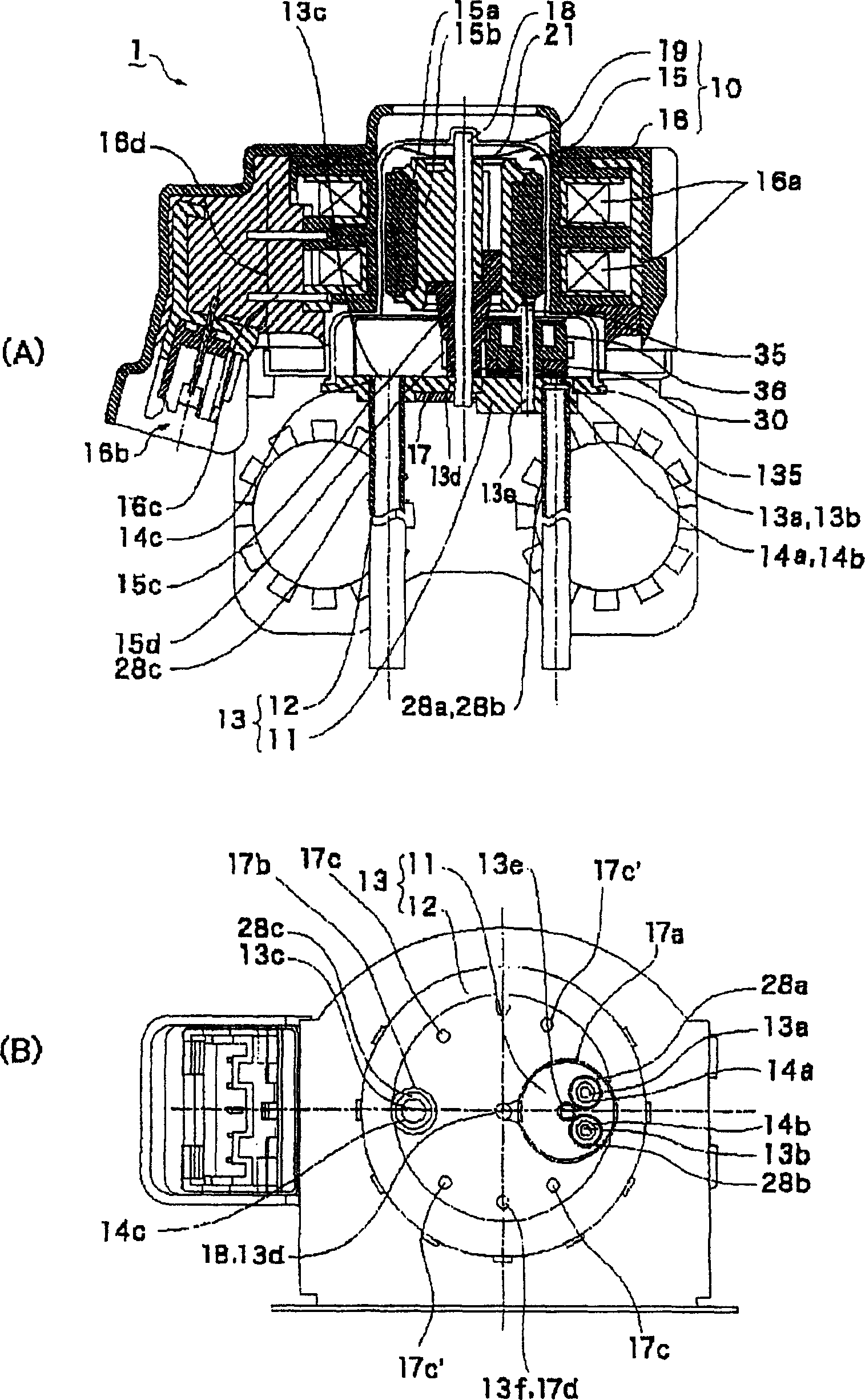
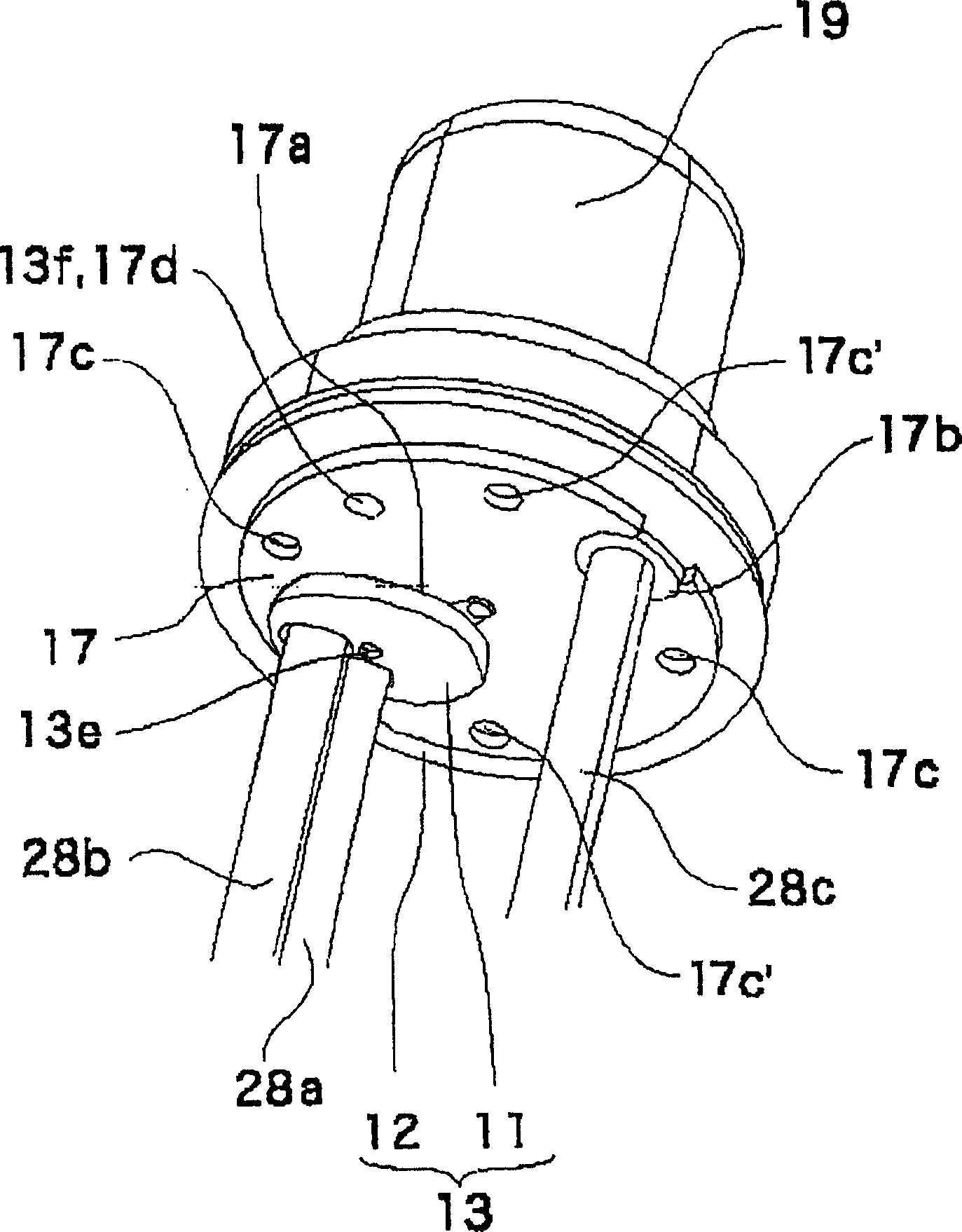
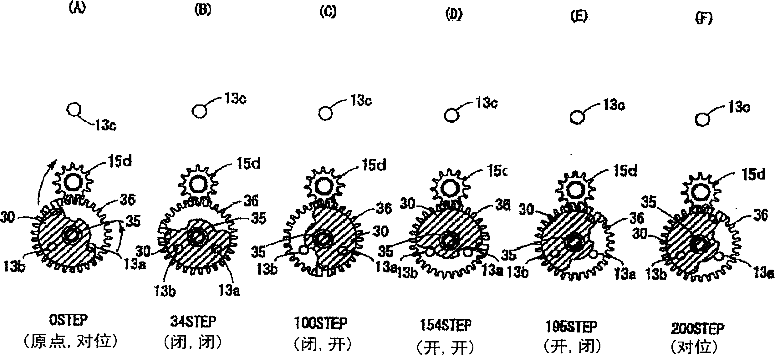
[0035] figure 1 (A), figure 1 (B) are a vertical sectional view and a bottom view of a valve driving device to which the present invention is applied, respectively. figure 2 It is a perspective view of a state in which the casing is sealed on the surface side cover of the valve seat plate as viewed obliquely from below. image 3 (A)~ image 3 (F) are figure 1 Explanatory diagrams for each mode of the valve actuator shown.

[0036] exist figure 1 Among them, the valve driving device 1 of the present embodiment includes a valve seat plate 13 and an airtight case 19 covered on the surface side of the valve seat plate 13 .

[0037] In this valve driving device 1 , a stepping motor 10 serving as a valve driving device that drives a valve body 30 is configured inside and outside a sealed case...


PUM


Abstract

To provide a valve drive device enabling to attach pipe to a part on which a valve element slides without generating deformation and capable of reducing manufacturing cost of a valve seat plate.The valve seat plate 13 of a valve device consists of a first plate structure member 11 constructing a zone where a flow out opening is formed, and a second plate structure member 12 to which the first plate structure member 1 is joined. The second plate structure member 12 is formed by press work, and includes a third plate structure member 17 for preventing deformation with resisting pressure in a sealed space defined by the valve seat plate 13 and a sealed case 19 on a back surface side thereof. The first plate structure member 11 is formed by cutting work of SUS material thicker than the second plate structure member 12.

Description

(1) Technical field [0001] The present invention relates to a valve driving device for opening and closing a plurality of opening valve bodies to distribute fluid. More specifically, it relates to the structure of the valve seat plate used in the valve driving device. (2) Background technology [0002] in the refrigerator, such as Figure 5 (A), Figure 5 As shown in (B), the valve driving device for distributing a common refrigerant (fluid) to a plurality of tanks for cooling to cool each tank includes: an inflow port 13c through which the refrigerant penetrates in the thickness direction; The valve seat plate 13' of the refrigerant outlet 13a, 13b; the airtight case (not shown) covering the surface side and the back side of the valve seat plate 13'; and the valve seat plate 13' A valve body (not shown) that opens and closes the outlet ports 13a, 13b by sliding on the surface. In addition, the rotor support shaft 18 and the valve body support shaft 35 are fixed to the val...

Claims


Application Information

Patent Timeline
Patent Type & Authority Applications(China)
IPC IPC(8): F16K11/074F16K31/04
CPCF16K11/0743F25B2600/2511F25B41/04F16K31/041Y10T137/86501F25B41/20F16K31/53
Inventor 原哲彦小泽滋
Owner SANKYO SEIKI MFG CO LTD
Why Eureka
Try Eureka