Rapid closure gate valve

A gate valve, fast technology, applied in the direction of sliding valve, valve details, valve device, etc., can solve the problems of long action time, inability to meet, unfavorable and fast shut-off, etc., to achieve the effect of reasonable and simple structure, convenient operation and cost reduction

Inactive Publication Date: 2013-06-12
WUHU JINMAO FLUID TECH CO LTD
View PDF1 Cites 0 Cited by
  • Summary
  • Abstract
  • Description
  • Claims
  • Application Information

AI Technical Summary

Problems solved by technology

However, the operation time of the opening and closing of the gate due to the rotation mode is relatively long, which is not conducive to the occasion of rapid closure
[0003] The patent number is 00219725.1, and the patent title is "Quick Gate Valve", which discloses a lever lift gate structure. However, the lever structure of this structure is cumbersome and the manufacturing process is complicated.
Therefore, the above two closure methods cannot meet the existing needs

Method used


Image

  • Rapid closure gate valve
  • Rapid closure gate valve
  • Rapid closure gate valve

Examples


Embodiment Construction

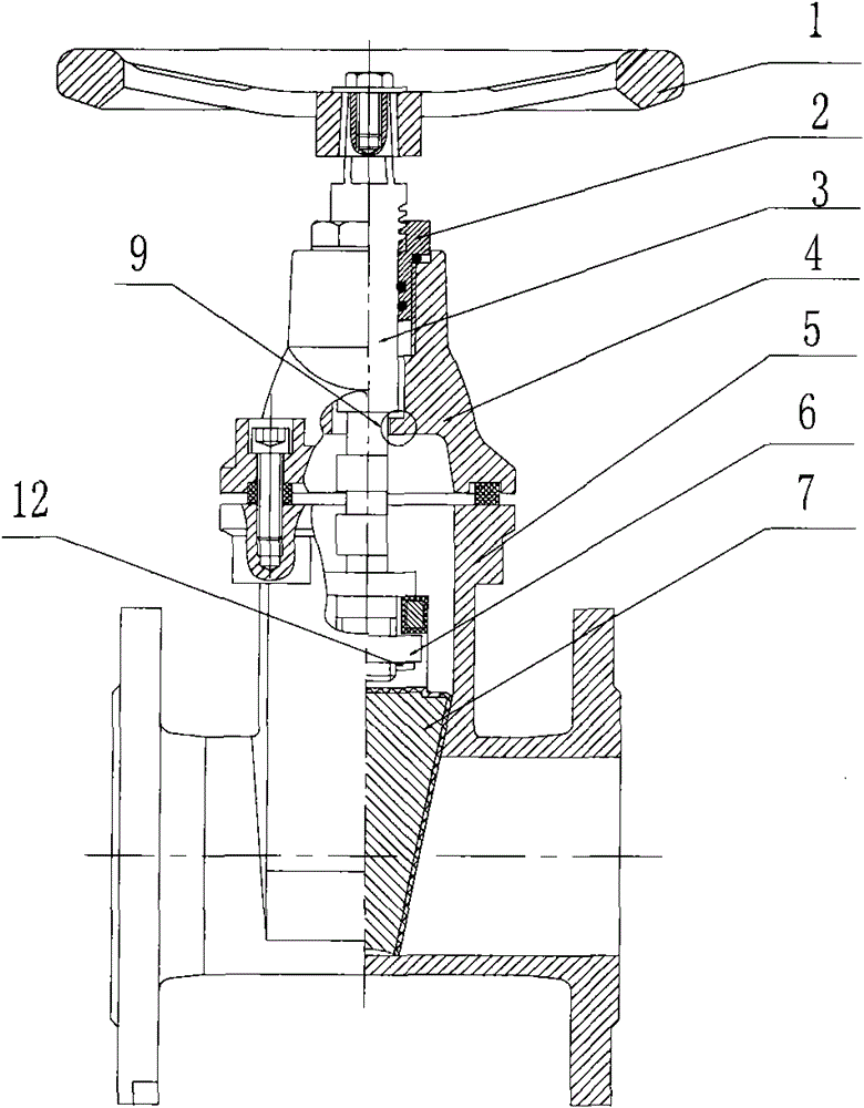
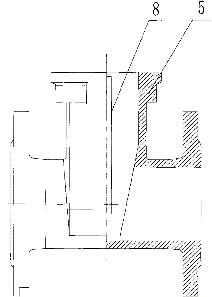
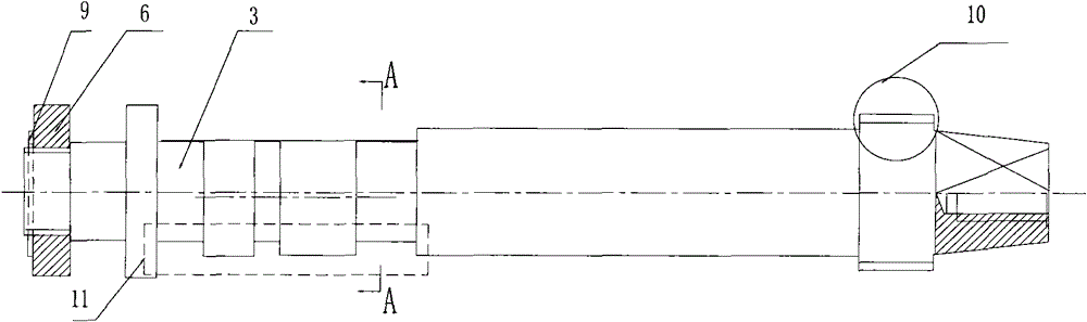
[0030] Depend on Figure 1-8 Combining the shown structures, it can be seen that this kind of fast shut-off gate valve includes a valve cover 4, a valve body 5, a gate plate 7 located at the bottom of the valve body 5 and wedge-shaped with the valve body 5, and a valve that runs through the valve cover 4 and the valve body 5. The valve stem 3 is in the hole and is movably connected with the top of the gate plate 7. The up and down movement of the valve stem 3 drives the gate plate 7 to quickly seal and open quickly. The valve cover 4 and the valve stem 3 are provided with a joint to control the opening size of the gate valve. Positioning device, wherein, the positioning device is provided with a boss 9 on the valve cover 4, and a notch 11 is provided on the valve stem 3 matching with the boss 9, and the notch 11 of the valve stem 3 is positioned on the boss 9. can be rotated.

[0031] As attached to the manual Figure 4 The structure shown is a structural schematic diagram o...


PUM


Abstract

The invention discloses a rapid closure gate valve. The gate valve comprises a valve cover, a valve body, a gate plate arranged on the bottom of the valve body and matched with the valve body in a wedge-shaped manner, and a valve rod penetrating through the valve cover and the inner hole of the valve body and movably connected with the top end of the gate plate, wherein the valve rod moves up anddown to drive the gate plate to be quickly sealed and opened; the valve cover and the valve rod are provided with a positioning device used for jointly coordinating to control the open degree of the gate valve; and the positioning device is provided with a boss on the valve cover, the cooperating position of the valve rod and the boss is provided with a notch, and the notch of the valve rod can rotate at the boss, the cross-sectional shape of the adjacent steps of the valve rod and the notch is round along a vertical axial direction, and the roundness is cut to form a side. The gate valve provided by the invention has the advantages that rapid closure and rapid open can be realized; a handle can be vertically lift up and down only by rotating the handle so as to enable the notch of the valve rod and the boss of the valve cover to be matched; the gate plate is driven by the valve rod to realize open and seal; and the gate plate is rotated an angle so as to stay at a position, and the operation is convenient and rapid.

Description

technical field [0001] The invention relates to a gate valve control mechanism, in particular to a fast cut-off gate valve capable of realizing fast cut-off control. Background technique [0002] In fluid pipeline control, a spool, also known as a ram, is usually used to intercept and control the fluid. In many valve series products, the rotation of the handle screw nut is usually used to drive the gate to open and close. However, it takes a long time to open and close the ram due to the rotation mode, which is not conducive to the occasion of rapid flow closure. [0003] The patent No. is 00219725.1, and the patent titled "Quick Gate Valve" discloses a lever lifting gate structure. However, the lever structure of this structure is loaded down with trivial details and the manufacturing process is complicated. Therefore, neither of the above two interception methods can meet the existing demand. Contents of the invention [0004] The technical problem to be solved by the...

Claims


Application Information

Patent Timeline
Patent Type & Authority Patents(China)
IPC IPC(8): F16K3/30F16K31/44F16K27/04F16K31/60
Inventor 孙述全陈旭东
Owner WUHU JINMAO FLUID TECH CO LTD
Why Eureka
Try Eureka