S-shaped spring of timer

A timer and clockwork technology, which is applied to the ratchet mechanism of the clockwork, winding the clockwork in a conventional way, instruments, etc., can solve the problems of affecting the speed of the gear rotation and reducing the accuracy of the timer travel time, etc.

Inactive Publication Date: 2012-02-01
宁波九菱电机有限公司
View PDF6 Cites 0 Cited by
  • Summary
  • Abstract
  • Description
  • Claims
  • Application Information

AI Technical Summary

Problems solved by technology

[0003] The mainsprings of existing timers are all rolled up in one direction. When the mainsprings are tightly wound and loosened, the force on the escape wheel on the gear set is first large and then small. In this way, the upper escapement of the gear set The speed of the wheel movement affects the speed of the gear rotation, resulting in a decrease in the accuracy of the timer travel time

Method used


Image

  • S-shaped spring of timer
  • S-shaped spring of timer
  • S-shaped spring of timer

Examples


Embodiment Construction

[0010] Below in conjunction with accompanying drawing and embodiment the invention will be further described:

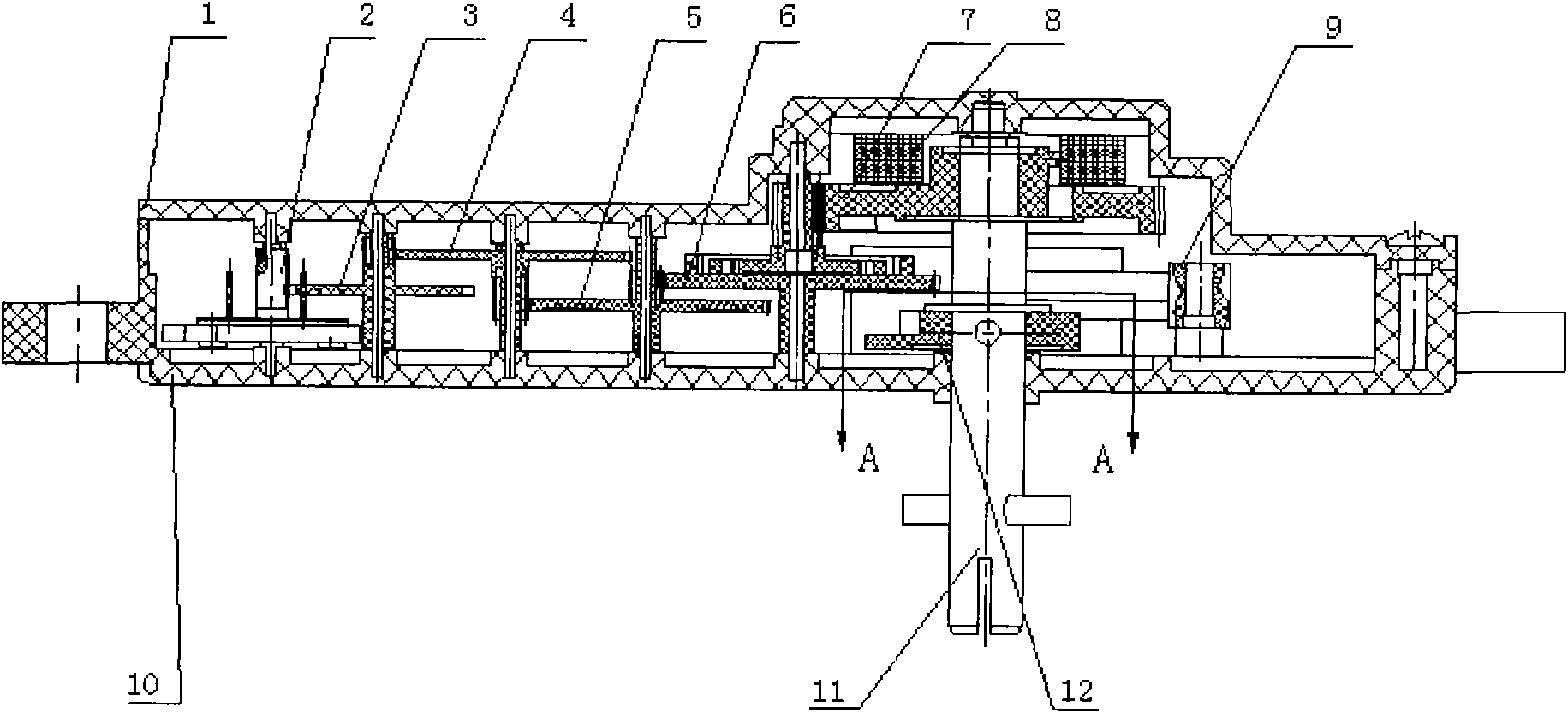
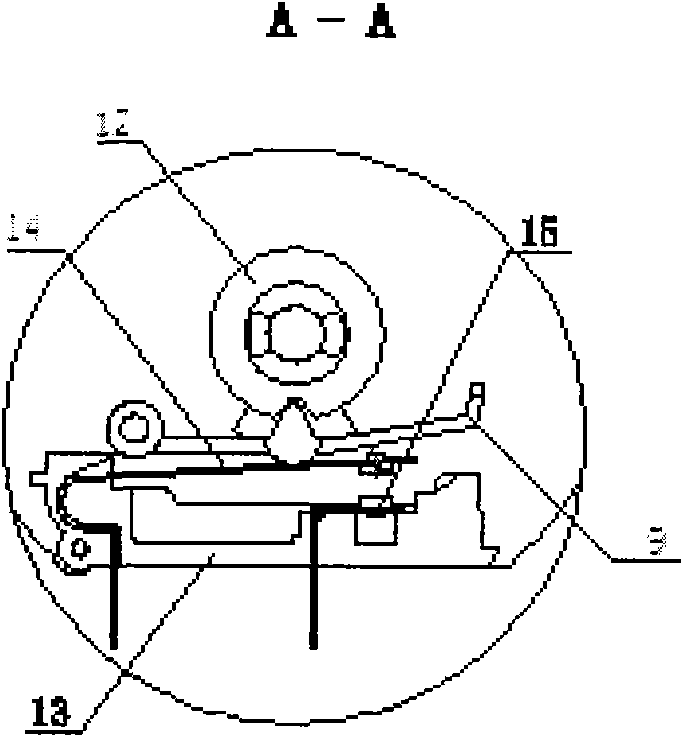
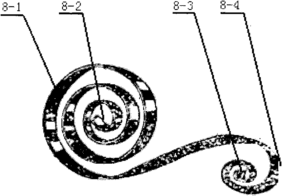
[0011] As shown in the figure, the housing of the timer is composed of the casing 1 and the base 10, and an S-shaped mainspring 8 is installed in the housing to connect the head wheel 7, the second wheel 6, the third wheel 5, and the fourth wheel 4 to realize speed-up. The longitudinal wheel 3 and the balance wheel 2 are released to control the time, and the timing is triggered by the lever 9, the cam 12, the breaking seat 13, the moving reed 14 and the static reed 15 breaking and closing. The S-shaped mainspring 8 is "S"-shaped no matter when it is loose or tight, and the moments of the inner and outer rings are mutually restrained, so that the output moments are always relatively balanced, so the escapement on the gear set The active force of the wheel is also relatively constant, which achieves the purpose of improving the accuracy of the timer travel time.


PUM


Abstract

The invention relates to a spring of a timer with high timing precision. The spring comprises a shell of the timer composed of a housing and a base; an S-shaped spring 8 in the shell is connected with a head wheel 7, a second wheel 6, a third wheel 5 and a fourth wheel 4 to achieve speed increase; the time is controlled by releasing an escape wheel 3 and a balance wheel 2; and the timing is controlled by switching on or off a lever 9, a cam 12, a break-make seat 13, a movable contact spring 14 and a fixed contact spring 15. Compared with the prior art, the spring is characterized by being S-shaped, and the external winded part of the spring is designed to opposite circles so as to obtain a large number of elastic deformation turns so that an output torque produced when the whole spring is released can be balanced and the torque of the escape wheel on a gear set is evenly stressed, and therefore, the timing precision of the timer is improved.

Description

technical field [0001] The invention relates to a spring, in particular to a timer spring with high travel time precision. Background technique [0002] The interior of the timer mainly includes three parts: the first part is the power part: it is composed of a clockwork and a one-way mechanism for winding, and the clockwork provides the power of the entire system. The second part is the release part: it consists of a set of speed change gears and escape wheel. The third part is a timing trigger device. When a certain gear in the gear set turns to a certain angle, it sends out a mechanical signal to control on-off. [0003] The springs of existing timers are all rolled up in one direction. When the springs are tightened and loosened, the force on the escape wheel on the gear set is first large and then small. In this way, the upper escapement of the gear set The speed of the wheel movement affects the speed of the gear rotation, resulting in a reduction in the accuracy of ...

Claims


Application Information

Patent Timeline
Patent Type & Authority Applications(China)
IPC IPC(8): G04B3/00
Inventor 金鹏伟鱼运禄黄雪波
Owner 宁波九菱电机有限公司
Why Eureka
Try Eureka