Capacitive touch board for improving linear response

A capacitive touch, linear response technology, applied in electrical digital data processing, data processing input/output process, instruments, etc., can solve the problem of low object positioning recognition rate, insignificant capacitance change, large Y coordinate nonlinearity response, etc.

Inactive Publication Date: 2012-02-01
ELAN MICROELECTRONICS CORPORATION
View PDF4 Cites 3 Cited by
  • Summary
  • Abstract
  • Description
  • Claims
  • Application Information

AI Technical Summary

Problems solved by technology

[0003] When the object is at position 10, although it touches the traces X2 and X3 in the X direction and the traces Y1 and Y2 in the Y direction at the same time, it has a relatively large contact area for the sensors X2 and Y2, and the capacitance change is obvious. The sensors X3 and Y1 have a smaller contact area, and the capacitance change is less obvious, so the calculated object position will be biased towards the coordinates (X2, Y2)
If the object moves from position 10 to position 12 along the X direction, the capacitance change in the Y direction will fluctuate, resulting in a large change in the analyzed Y coordinate and a large nonlinear response, resulting in a lower object location resolution

Method used


Image

  • Capacitive touch board for improving linear response
  • Capacitive touch board for improving linear response
  • Capacitive touch board for improving linear response

Examples


no. 1 example

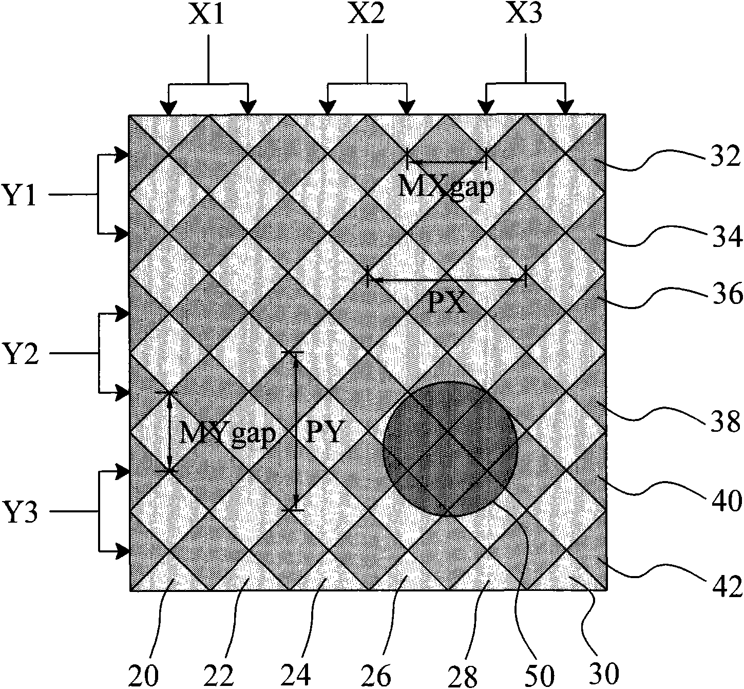
[0014] figure 2 According to the first embodiment of the present invention, the capacitive touch panel has a plurality of parallel traces 20, 22, 24, 26, 28 and 30 in the X direction and a plurality of parallel traces 32, 34, 36, 36 in the Y direction. 38, 40 and 42, wherein the traces 20 and 22 are electrically connected to form the sensor X1 in the X direction, the traces 24 and 26 are electrically connected to form the sensor X2 in the X direction, and the traces 28 and 30 are electrically connected to form the X direction Traces 32 and 34 are electrically connected to form an inductor Y1 in the Y direction, traces 36 and 38 are electrically connected to form an inductor Y2 in the Y direction, traces 40 and 42 are electrically connected to form a sensor in the Y direction Device Y3. The traces in the X direction and the Y direction can be electrically connected inside or outside the touch panel to form a sensor. The distance between the centers of adjacent inductors in t...


PUM


Abstract

The invention discloses a capacitive touch board for improving linear response, which is invented for improving the linear response of the capacitive touch board. The capacitive touch board comprises a plurality of sensors, wherein each sensor is provided with a plurality of parallel adjacent traces; a certain distance is reserved between the centers of adjacent sensors; and a maximum gap smaller than the distance is reserved between adjacent traces. By adopting the structure, the maximum gaps MXgap and Mygap between the adjacent traces are respectively smaller than PX and PY, so that the capacitance variation linearly changes more stably whether the capacitance variation moves towards X direction or Y direction and further the linear response of the capacitive touch board is improved.

Description

technical field [0001] The invention relates to a capacitive touch panel, in particular to a capacitive touch panel with improved linear response. Background technique [0002] Such as figure 1 As shown, the conventional two-dimensional capacitive touch panel utilizes a plurality of sensors X1, X2 and X3 in the X direction and a plurality of sensors Y1, Y2 and Y3 in the Y direction to detect the touch of the object, each sensing The sensor is composed of a trace (trace), and each trace is formed by connecting multiple rhombic electrode plates in series to maximize the trace area, where the distance between the centers of adjacent sensors in the X direction is PX , the maximum gap between adjacent traces in the X direction is MXgap, the distance between the centers of adjacent sensors in the Y direction is PY, the maximum gap between adjacent traces in the Y direction is MYgap, and the maximum gap MXgap and MYgap are equal to PX and PY respectively. The capacitive touch pa...

Claims


Application Information

Patent Timeline
Patent Type & Authority Applications(China)
IPC IPC(8): G06F3/044
Inventor 陶逸欣林嘉兴许文俊
Owner ELAN MICROELECTRONICS CORPORATION
Why Eureka
Try Eureka