

Interference filter, optical module, and analyzing device
An interference filter and analysis device technology, applied in the field of interference filters, can solve the problems of lower reflectivity, performance degradation of interference filters, etc., and achieve the effect of suppressing performance degradation
- Summary
- Abstract
- Description
- Claims
- Application Information
AI Technical Summary
Problems solved by technology
Method used
Image

Examples
no. 1 approach
[0038] (1. The overall structure of the color measurement device)
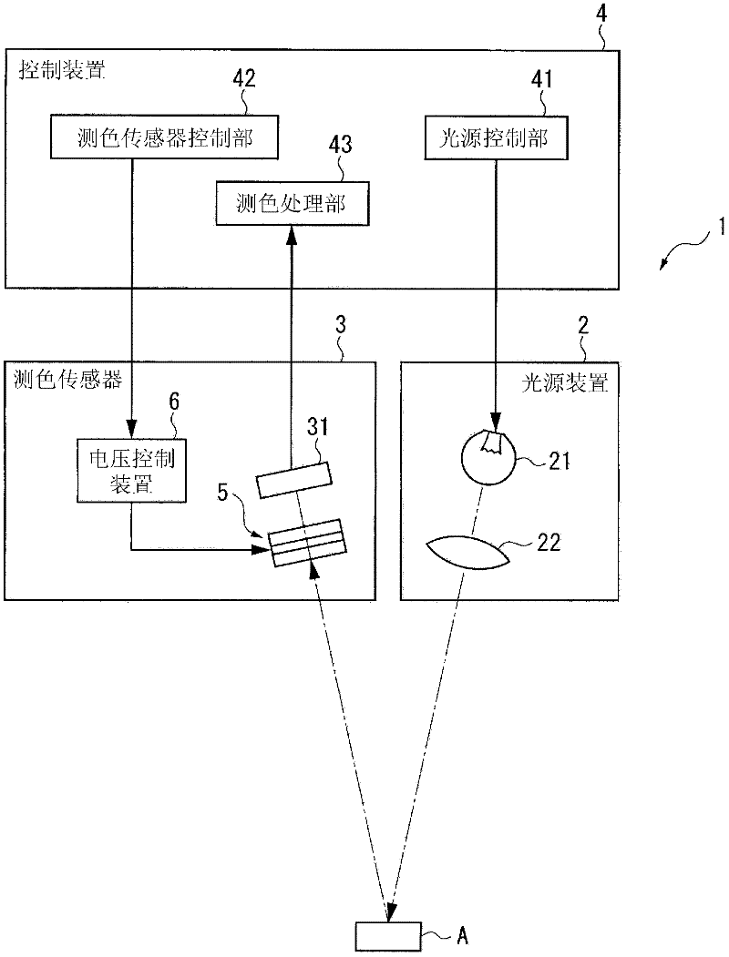
[0039] figure 1 It is a diagram showing a schematic configuration of a colorimetric device according to an embodiment of the present invention.
[0040] The colorimetric device 1 is an analysis device of the present invention, such as figure 1 As shown, it includes a light source device 2 that emits light to an object A to be inspected, a colorimetric sensor 3 as an optical module of the present invention, and a control device 4 that controls the overall operation of the colorimetric device 1 . In addition, in this colorimetric device 1, the light emitted from the light source device 2 is reflected by the inspection object A, the reflected inspection object light is received by the colorimetric sensor 3, and the detection signal of the inspection object light is detected based on the detection signal output from the colorimetric sensor 3. Chromaticity is a device for analyzing and measuring the color of the ...
no. 2 approach
[0118] Next, a second embodiment according to the present invention will be described.
[0119] Here, in the description of the second embodiment, the same components as those of the first embodiment are denoted by the same symbols, and the description thereof will be omitted or simplified.
[0120] The second embodiment differs from the etalon 5 of the first embodiment in that the fixed mirror 56 and the movable mirror 57 of the etalon 5A include dielectric films 561 and 571 and alloy films 562 and 572 . The alloy films 562 and 572 are the same as those of the first embodiment.
[0121] Such as Figure 4As shown, on the first substrate 51 , a dielectric film 561 and an alloy film 562 are provided sequentially from the first substrate 51 . That is, the dielectric film 561 is provided between the first substrate 51 and the alloy film 562 . Likewise, on the second substrate 52 , a dielectric film 571 and an alloy film 572 are provided sequentially from the second substrate 52...
no. 3 approach
[0127] Next, a third embodiment according to the present invention will be described.
[0128] Here, in the description of the third embodiment, the same components as those of the first embodiment and the second embodiment are denoted by the same reference numerals, and the description thereof is omitted or simplified.
[0129] The third embodiment differs from the first embodiment in that the fixed mirror 56 and the movable mirror 57 of the etalon 5B include protective films 563 and 573 in addition to the dielectric films 561 and 571 and the alloy films 562 and 572. The etalon 5 of the second embodiment is different from the etalon 5A of the second embodiment. The alloy films 562 and 572 are the same as those of the first embodiment. The dielectric films 561 and 571 are the same as those of the second embodiment.
[0130] Such as Figure 5 As shown, on the first substrate 51 , a dielectric film 561 , an alloy film 562 , and a protective film 563 are sequentially provided ...
PUM
| Property | Measurement | Unit |
|---|---|---|
| thickness | aaaaa | aaaaa |
| thickness | aaaaa | aaaaa |
| thickness | aaaaa | aaaaa |
Abstract
Description
Claims
Application Information