
Method and equipment for selecting sampling clock signal

A sampling clock and clock signal technology, applied in the field of network communication, can solve the problems of poor system maintainability and high operation and maintenance costs, and achieve the effect of improving maintainability and reducing maintenance costs

Active Publication Date: 2012-02-08
HUAWEI TECH CO LTD
View PDF14 Cites 14 Cited by
  • Summary
  • Abstract
  • Description
  • Claims
  • Application Information

AI Technical Summary

Benefits of technology

The technology described in this patented method allows for accurate detection of both edges' positions on an integrated circuit (IC) device during manufacturing or testing stages. This helps reduce costs while maintaining reliable performance over time.

Problems solved by technology

This patented technical problem addressed in the patents relates to improving the performance and reliance of transmitting signals over long distances without causing errors during transmission.

Method used


Image

  • Method and equipment for selecting sampling clock signal
  • Method and equipment for selecting sampling clock signal
  • Method and equipment for selecting sampling clock signal

Examples


Embodiment Construction

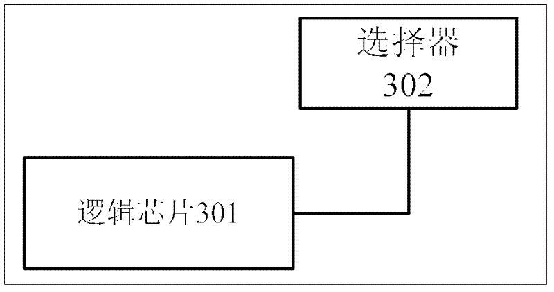
[0019] see figure 1 , is a flowchart of a method for selecting a sampling clock signal provided by an embodiment of the present invention. The method for selecting a sampling clock signal is applied to a receiving end device, and the receiving end device includes a logic chip and a selector. The logic chip Connected with the selector; the method for selecting the sampling clock signal includes:

[0020] 101: The logic chip acquires a data edge of a data signal and a clock edge of a clock signal, selects a sampling edge according to the data edge and the clock edge, and sends a selection signal corresponding to the sampling edge to the selector.

[0021] The receiver device may be data terminal equipment (Data Terminal Equipment, DTE for short) or data communication equipment (Data Communication Equipment, DCE for short).

[0022] The logic chip can be a complex programmable logic device (Complex Programmable Logic Device, referred to as CPLD), a field-programmable gate array ...


PUM


Abstract

The embodiment of the invention discloses a method and equipment for selecting a sampling clock signal. The method comprises the following steps: a logical chip acquires a data edge of a data signal and a clock edge of a clock signal, selects a sampling edge according to the data edge and the clock edge, and transmits a selection signal corresponding to the sampling edge to a selector; and the selector selects a sampling clock signal according to the selection signal. By adopting the technical scheme disclosed by the embodiment of the invention, the problems of poor system maintainability and high operation maintenance cost due to the fact that receiving end equipment selects the sampling clock signal by virtue of manual configuration in the existing synchronous serial interface communication can be solved.

Description


Claims


Application Information

Patent Timeline
Owner HUAWEI TECH CO LTD
Learn More