
Vortex flow measuring device for monitoring and/or measuring a distributed particle and/or droplet flow

A measuring device, eddy current technology, applied in the direction of measuring flow/mass flow, measuring device, volume/mass flow generated by mechanical effects, etc., can solve problems such as increased cost and labor

Inactive Publication Date: 2012-02-08
ENDRESS HAUSER FLOWTEC AG
View PDF4 Cites 9 Cited by
  • Summary
  • Abstract
  • Description
  • Claims
  • Application Information

AI Technical Summary

Problems solved by technology

This results in increased cost and labor

Method used


Image

  • Vortex flow measuring device for monitoring and/or measuring a distributed particle and/or droplet flow
  • Vortex flow measuring device for monitoring and/or measuring a distributed particle and/or droplet flow
  • Vortex flow measuring device for monitoring and/or measuring a distributed particle and/or droplet flow

Examples


Embodiment Construction

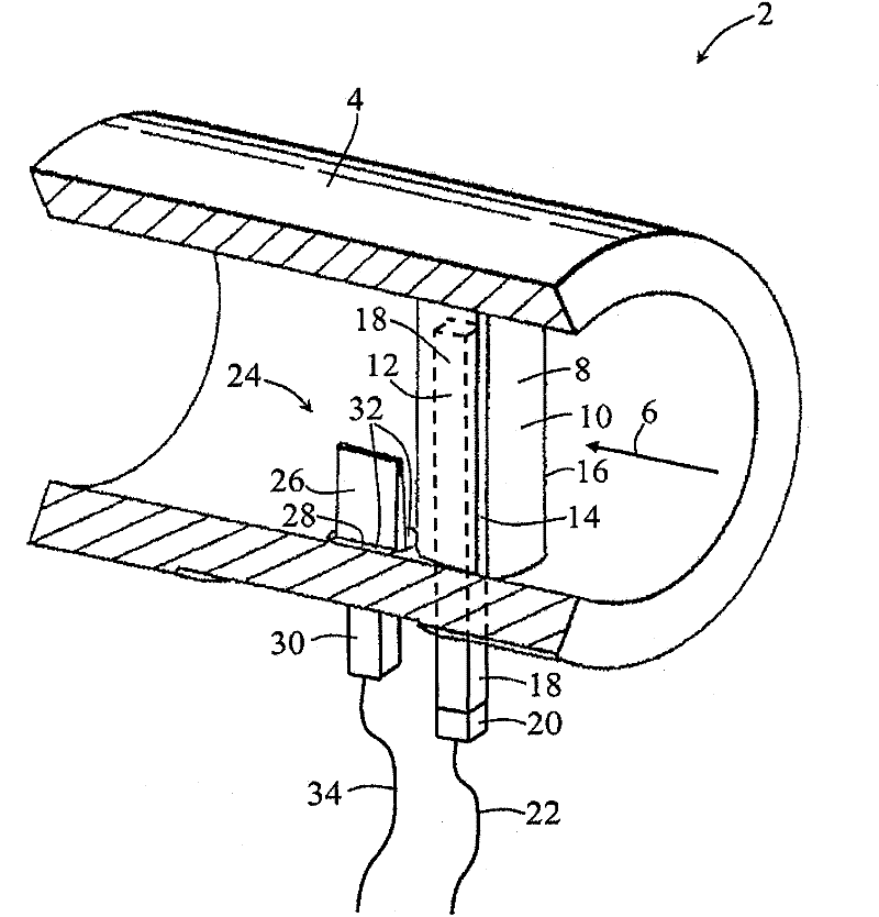
[0099] figure 1 An eddy current measuring device 2 in the form of an embodiment according to the invention is shown schematically and in perspective. The eddy current measuring device 2 comprises a measuring tube 4 which is in figure 1 Shown in partial section. In use, the measuring tube 4 is inserted into a pipeline (not shown) in which the flow of a first fluid (here: gas) is to be determined, so that the first fluid (corresponding to the "first phase") flows through the measuring tube in the flow direction 6 Tube.

[0100] The eddy current measuring device 2 comprises a bluff body 8 which extends diametrically across the total inner cross-section of the measuring tube 4 . In this case, the bluff body 8 is embodied with an impingement area 10 on the side facing the flow; the first fluid and the stream of particles and / or droplets flow onto the impingement area for the impact to occur. The impingement region is bounded on both sides by side surfaces 12 , wherein both si...


PUM


Abstract

The present invention relates to a vortex flow measuring device (2) for monitoring and / or measuring an at least intermittently two-phase medium flowing in a pipeline, which medium comprises an in particular gaseous first phase having a first density and a second in particular particulate or droplet phase having a second density different from the first density, wherein the vortex flow measuring device (2) comprises at least one measurement pipe (4) that can be inserted into a pipeline, a bluff body (8), and a vortex sensor (24) that responds to pressure oscillations that occur.; The vortex flow measuring device (2) comprises an acoustic transducer (20), which is integrally designed in a component (8) of the vortex flow measuring device that protrudes into a flow path inside the measurement pipe (4), in particular in the bluff body (8), in such a way or is acoustically coupled to said component (8) in such a way that acoustic signals generated by the impact of particles and / or droplets of the second phase onto the component (8) can be converted into electrical signals by the acoustic transducer (20).

Description

technical field [0001] The invention relates to an eddy current measuring device as defined in the preamble of claim 1 and to a method of monitoring and / or measuring a medium flowing in a pipeline and at least sometimes having at least two phases, a first of the two phases, The first phase, in particular gaseous, has a first density, and the second phase, especially in the form of particles or droplets, has a second density different from the first density. The method is carried out with a bluff body protruding into the flowing medium and in particular an eddy current sensor placed downstream of or within the bluff body. Background technique [0002] Eddy current measuring devices are often used to measure the flow of fluids in pipelines, especially gas or vapor flows in the high temperature range. In the case of such eddy current measuring devices, a baffle is arranged in the flow path such that fluid can flow on both sides of the baffle. In this case, eddies are formed o...

Claims


Application Information

Patent Timeline
Patent Type & Authority Applications(China)
IPC IPC(8): G01F1/32G01F1/74
CPCG01F1/666G01F1/74G01F1/3209G01F1/3266G01F1/3218
Inventor 皮特·利马谢赖纳·霍克德克·聚特林克里斯托弗·戈斯魏勒
Owner ENDRESS HAUSER FLOWTEC AG
Learn More