Gas-liquid rotary turbine separation device

A separation device and gas-liquid technology, applied in the field of gas-liquid rotary turbine separation device, can solve the problems of not being able to ensure efficient utilization of fluid pressure energy, useful energy consumption of multiphase fluids, and reducing secondary mixing, etc. Small, minimizes gas entrainment and liquid carryover, reduces the effect of remixing

Inactive Publication Date: 2012-02-15
CHINA UNIV OF PETROLEUM (EAST CHINA)
View PDF4 Cites 0 Cited by
  • Summary
  • Abstract
  • Description
  • Claims
  • Application Information

AI Technical Summary

Problems solved by technology

[0002] In the petroleum industry, the traditional gas-liquid two-phase separation technology has been well developed, but there are three main problems: one is that the traditional separation equipment is bulky and heavy; the other is that the useful energy in the multiphase fluid is partially or completely consumed; the third is that when foam and emulsification are produced, the separation is not complete
[0004] The pressure energy conversion device in the hybrid two-phase turbine in the Hays patent - the gas-liquid two-phase nozzle, is realized by an irregular flow channel with an adjustable throat cross-sectional area. Although it can achieve a certain degree of flow regulation, it cannot guarantee the fluid Efficient use of pressure energy; the separated liquid film is always in contact with the gas, which is not conducive to reducing the secondary mixing; the gas blades of the separator adopt axial blades, the overall length is large, and the floor area is large

Method used


Image

  • Gas-liquid rotary turbine separation device
  • Gas-liquid rotary turbine separation device
  • Gas-liquid rotary turbine separation device

Examples


Embodiment

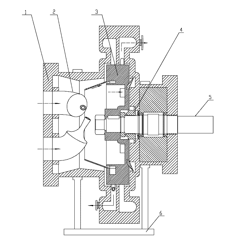
[0026] as attached figure 1 , 5 As shown, the present invention mainly includes a casing 1 as a gas-liquid discharge device, a gas-liquid two-phase nozzle 2, a separation rotor 3, a sealing and lubricating device 4, a separator shaft 5, and a separator support 6. The cavity in the housing 1 is an axially horizontal rotationally symmetrical structure, and the cavity of the housing 1 is provided with a separator shaft 5 fixed in the cavity through a sealing and lubricating device 4 from right to left. 5. One end protrudes from the shell 1, and the other end is fixed with the separation rotor 3 and is located in the middle of the cavity. On the left side of the separation rotor 3, a gas-liquid two-phase nozzle 2 is fixed on the left end of the shell 1. The whole invention is an axial "building block" installation, which is beneficial to the maintenance of the separator and the replacement of parts.

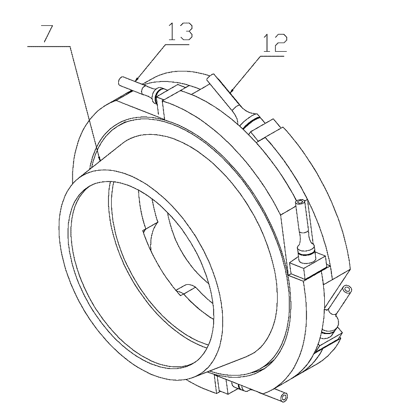
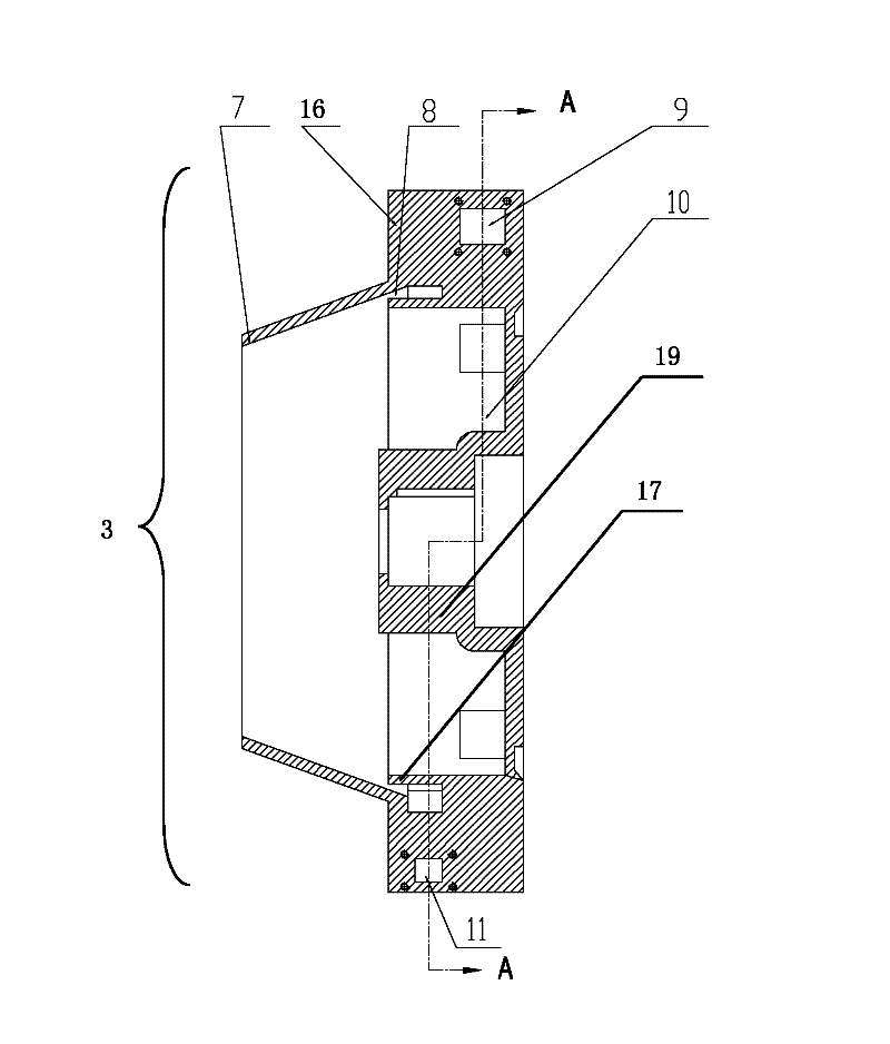
[0027] as attached Figure 2~4 As shown, the separation rotor 3 of the presen...


PUM


Abstract

The invention relates to a gas-liquid rotary turbine separation device, which comprises a hollow shell arranged on a support and a rotating shaft which is fixed in the shell by a sealing and lubricating device, wherein one end of the rotating shaft extends out of the shell, and a separation rotor positioned on the middle part of an inner cavity of the shell is fixed to the other end of the rotating shaft; and a gas-liquid two-phase spray nozzle is formed at one end, which is adjacent to the separation rotor, of the shell. The gas-liquid rotary turbine separation device is characterized in that the separation rotor comprises a separation disc which is fixed to the rotating shaft and is provided with an annular liquid collecting tank and an annular air collecting cavity sequentially and axially; the liquid collecting tank is connected with a separation cone; the liquid collecting tank and the air collecting cavity are communicated with a liquid reverse action spray nozzle and an air reverse action spray nozzle; an annular partition plate is arranged between the liquid collecting tank and the air collecting cavity; and a liquid spiral case and an air spiral case which are partitioned by the partition plate are arranged on the middle part of the inner cavity of the shell axially side by side. The gas-liquid rotary turbine separation device has a reasonable structure, is novel in design, high in separation efficiency and convenient to disassemble and maintain and is arranged in an axial cordwood mode, and the floor space is reduced by reducing axial geometric dimensions.

Description

technical field [0001] The invention relates to a gas-liquid separation device, in particular to a gas-liquid rotating turbine separation device, and belongs to the technical field of oil-gas separation and natural gas dehydration in oil-gas gathering and transportation systems. Background technique [0002] In the petroleum industry, the traditional gas-liquid two-phase separation technology has been well developed, but there are three main problems: one is that the traditional separation equipment is bulky and heavy; the other is that the useful energy in the multiphase fluid is partially or completely consumed; the third is that when foam and emulsification are produced, the separation is not complete. With the development of my country's oil and gas industry, especially the development of offshore oil and gas fields, oil and gas separators have developed from the traditional gravity type to the direction of high efficiency, compactness and energy saving. China's small se...

Claims


Application Information

Patent Timeline
Patent Type & Authority Applications(China)
IPC IPC(8): B01D45/14B01D19/00
Inventor 何利民王天祥吕宇玲罗小明王鑫刘超
Owner CHINA UNIV OF PETROLEUM (EAST CHINA)
Why Eureka
Try Eureka