Automatically adjustable stroke type brake cylinder of railway vehicle

An automatic adjustment, railway vehicle technology, applied in the direction of brake actuators, slack adjusters, etc., can solve the problems of low operational reliability, easy automatic failure, cumbersome and complex structure, etc., to improve transmission efficiency and operational reliability , simple structure and high transmission efficiency

Active Publication Date: 2012-02-15
CRRC ZHUZHOU ROLLING CO LTD
View PDF6 Cites 14 Cited by
  • Summary
  • Abstract
  • Description
  • Claims
  • Application Information

AI Technical Summary

Problems solved by technology

[0004] At present, on some traditional railway vehicles with a relatively large space for the brake device, the brake cylinder and the brake shoe clearance adjustment mechanism in the brake device are arranged separately, and the brake cylinder and the brake shoe clearance adjustment mechanism are arranged through a A series of levers, connecting rods and other transmission parts are connected, not only the structure is complicated, the space is large, the production cost is high, but also the transmission efficiency is low and the work reliability is poor.
However, on some new railway vehicles where the layout space of the brake device is limited, it is very difficult to arrange the brake cylinder and the brake shoe clearance adjustment mechanism separately. Even if the arrangement is barely completed, it still has complicated structure, low transmission efficiency and reliable operation Low performance, easy to produce defects such as automatic failure

Method used


Image

  • Automatically adjustable stroke type brake cylinder of railway vehicle
  • Automatically adjustable stroke type brake cylinder of railway vehicle
  • Automatically adjustable stroke type brake cylinder of railway vehicle

Examples


Embodiment Construction

[0023] The railway vehicle automatic stroke adjustment type brake cylinder of the present invention will be further described in detail below in conjunction with the accompanying drawings and specific embodiments.

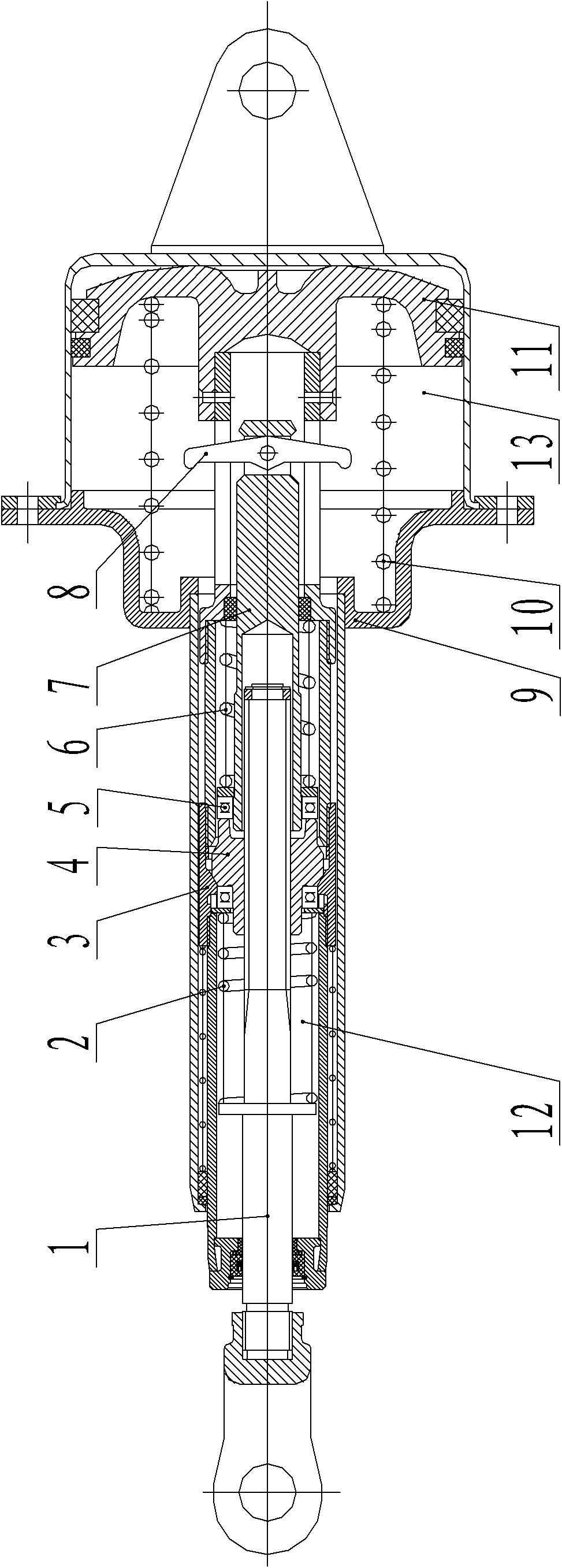
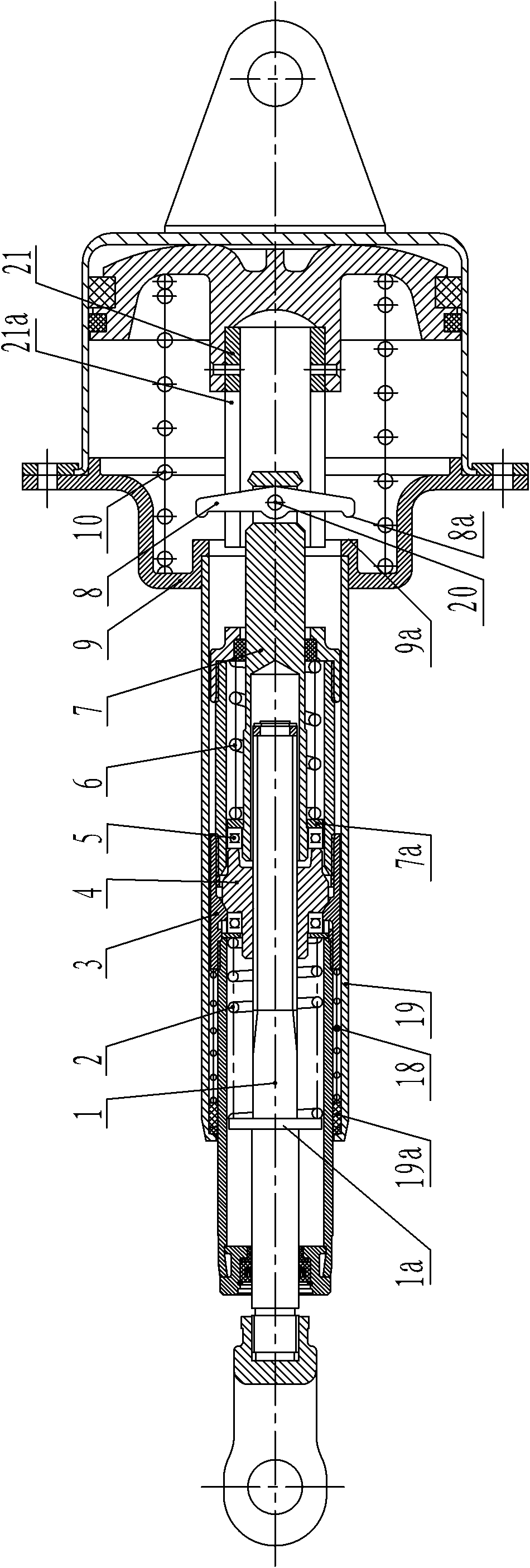
[0024] see Figure 1(a) to Figure 1(c) ,as well as figure 2 , The railway vehicle automatic adjustment stroke type brake cylinder of the present invention is mainly composed of a brake cylinder body 13 and a brake shoe clearance adjustment mechanism 12. Wherein: the brake cylinder body 13 has a cylinder body 9, a piston 11 is installed in the cylinder body 9, a relief spring 10 is arranged between the piston 11 and the cylinder body 9, and a push sleeve 21 is rigidly connected to the piston 11 through a riveting structure. The top of the cylinder body 9 is connected with an outer sleeve 19 communicating with its inner cavity, and the top of the push sleeve 21 is symmetrically provided with two guide grooves 21 a, and the top of the push sleeve 21 can be pushed int...


PUM


Abstract

The invention discloses an automatically adjustable stroke type brake cylinder of a railway vehicle, which mainly comprises a brake cylinder body and a brake shoe gap adjusting mechanism. The brake cylinder body comprises a cylinder body, a piston, a release spring and a pushing sleeve connected with the piston; the top end of the cylinder body is provided with an outer sleeve; and the top of thepushing sleeve is provided with a guide groove and can be pushed into the outer sleeve. The brake shoe gap adjusting mechanism comprises a screw rod, a first spring, a combined sleeve, an adjusting nut, a second spring, a pull rod and a control lever, wherein the combined sleeve can be installed in the outer sleeve in an axial moving way; the combined sleeve supports against the pushing sleeve under the action of an offsetting spring, the pull rod is connected with the control lever, the control lever is embedded in the guide groove of the pushing sleeve, and a boss at the end part of the control lever can be matched with a boss in an inner cavity of the cylinder body in a supporting way. The automatically adjustable stroke type brake cylinder of the railway vehicle is simple and compact in structure, reliable in operation performance and high in transmission efficiency and can meet the requirement for stable working strokes of brake cylinders of most of railway vehicles and improve the safety in operation of the railway vehicle.

Description

technical field [0001] The invention relates to a braking device for a railway vehicle, in particular to an automatic stroke-adjusting brake cylinder for a railway vehicle. Background technique [0002] In a railway vehicle braking device, the performance of the brake cylinder has a great influence on the reliability and service life of the entire braking system. For a vehicle with an excessively long piston stroke in the brake cylinder, its braking force will be reduced, and at the same time, the braking will lag behind that of other vehicles with normal piston strokes. For vehicles with too short piston strokes in the brake cylinder, the braking force will be increased, and the braking will be advanced compared to other vehicles with normal piston strokes. Regardless of braking lag or braking advance, the longitudinal impact of the train will increase. In today's heavy-duty high-speed running mode of vehicles, it is very important to keep the stroke of the brake cylinder...

Claims


Application Information

Patent Timeline
Patent Type & Authority Applications(China)
IPC IPC(8): F16D65/14F16D65/66
Inventor 马驰涂智文王宝磊易新炳
Owner CRRC ZHUZHOU ROLLING CO LTD
Why Eureka
Try Eureka