
Fast water draining mechanism suitable for water tank

A drainage mechanism and water tank technology, which is applied to flushing equipment with water tanks, water supply devices, buildings, etc., can solve the problems of limited drainage flow, slow drainage speed, and complicated seals, and achieve clear direction, convenient and reliable installation, and quantity little effect

Active Publication Date: 2013-11-06
XIAMEN R&T PLUMBING TECH
View PDF5 Cites 0 Cited by
  • Summary
  • Abstract
  • Description
  • Claims
  • Application Information

AI Technical Summary

Problems solved by technology

However, this type of solution still has its disadvantages: the seal is complicated, easy to block and jam, and the drainage flow is limited, resulting in a slower drainage speed

Method used


Image

  • Fast water draining mechanism suitable for water tank
  • Fast water draining mechanism suitable for water tank
  • Fast water draining mechanism suitable for water tank

Examples


Embodiment Construction

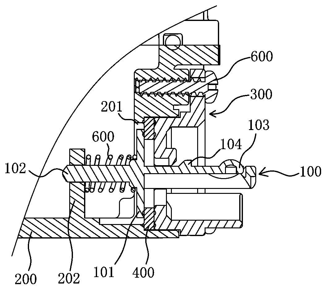
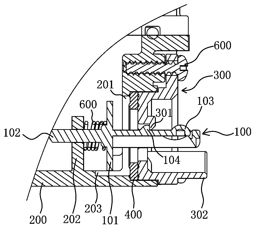
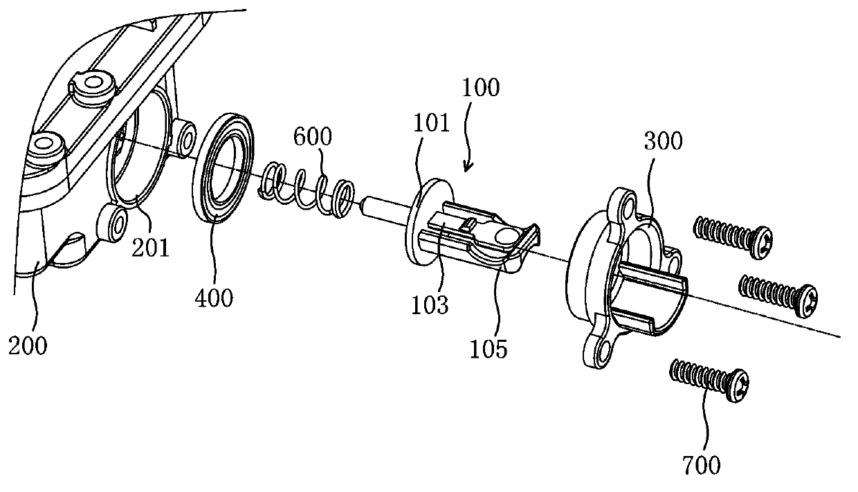
[0027] like figure 1 , a longitudinal sectional view of the embodiment of the present invention, which shows the water-stop state of the entire drainage mechanism; from the composition of the figure, the entire mechanism is located at the bottom side of the water tank 200; there is a drainage hole 201 on the side of the water tank 200 here, The normal direction of the drainage hole 201 is horizontal; the drainage core 100 is in the axial direction, and from left to right in the figure are the guide rod 102, the sealing disc 101 and the shrapnel 103, and the shrapnel 103 also has a boss 104;

[0028] Outside the drain hole 201 , a gland 300 is fixed with a screw 700 , and the gland 300 is pressed onto the drain hole 201 through a gasket 400 ; and, the gland 300 has a through hole corresponding to the drain hole 201 .

[0029] The shrapnel 103 of the drainage core 100 is connected through the through hole of the gland 300 and the drainage hole 201; at the same time, the guide ro...


PUM


Abstract

The invention discloses a fast water draining mechanism suitable for a water tank. The water draining mechanism suitable for the water tank is characterized by comprising one row of water draining holes and a water draining core, wherein the water draining holes are positioned at the side surface of the bottom of the water tank; the water draining core comprises a sealing disc as well as a guide rod and an elastic sheet; the guide rod and the elastic sheet are fixedly connected with the two bottom surfaces of the sealing disc respectively; one face of the elastic sheet is provided with a boss; and a press cover with a sealing pad is arranged; a through hole is formed at the centre of the press cover; the press cover is fixed outside the water draining holes, wherein the elastic sheet of the water draining core penetrates into the through hole of the press cover and the water draining holes; the guide rod is sleeved with a return spring and movably fitted in a rod sleeve fixed together with the water tank; and the through hole of the press cover is also provided with a clamping buckle capable of limiting the boss while the sealing disc is far away from the sealing pad. By using the water draining core with the elastic sheet, the water can be very quickly drained and stopped by hand under the mutual effect of the guide rod and the return spring.

Description

technical field [0001] The invention relates to a drainage device for a bathroom water tank, in particular to a fast drainage mechanism suitable for the water tank. Background technique [0002] Water tanks in the field of bathroom equipment, especially the water tanks built into many smart covers, include functions such as heating, water inlets, and drains. In order to prevent the washing water stored in the water tank from freezing, it is necessary Drain in time, so there is a drainage hole and a water stopper on the left or right side of the lower part of the water tank, as shown in Figure 10 in patent 200910172907.5, in order to achieve drainage and water stop, you must use tools to unscrew the water stopper to achieve drainage , tighten to achieve water stop. [0003] There is another kind of solution, such as a drainage device for a box disclosed in CN200920196596, which can complete drainage and water stop with bare hands, which makes the operation easy and eliminate...

Claims


Application Information

Patent Timeline
Patent Type & Authority Patents(China)
IPC IPC(8): E03D1/34
Inventor 谢伟泉王兵
Owner XIAMEN R&T PLUMBING TECH
Learn More