Rotating shaft structure for display folding bracket

A technology of folding bracket and shaft structure, which is applied in the direction of machine platform/bracket, supporting machine, pivot connection, etc., which can solve the problems of affecting the viewing angle of the display, uneasy rotation, and short service life, so as to expand the scope of installation and use, meet Angle requirements, the effect of meeting audio-visual needs

Active Publication Date: 2014-03-26
TAIZHOU STRONKIN ELECTRONICS
View PDF8 Cites 0 Cited by
  • Summary
  • Abstract
  • Description
  • Claims
  • Application Information

AI Technical Summary

Problems solved by technology

[0003] However, the rotating shaft structure connected between the display mounting plate and the lifting die-casting of the existing display folding support is generally formed by a combination of shaft center, shrapnel, spacers and angle spacers. The rotating shaft of this structure rotates on the display mounting plate. It is easy to produce a sense of stagnation, which is inconvenient to use, and the gasket and shrapnel are combined to achieve the elastic effect, the rotation is not free, light or heavy, the service life is short, the production cost is high, and it is difficult to meet the viewing angle requirements of the display
[0004] In addition, there are also torsion springs arranged on the rotating shaft, and the torsion spring is provided with one, and the display mounting plate plays a certain role within a certain range when the display mounting plate is rotated from a vertical state, such as playing an elastic role within 0-30 degrees, or when rotating, the elastic force Strong or weak, as the rotation angle increases, the elastic force gradually loses or increases gradually, and the elastic force is unstable. It will lose the elastic force in a certain rotation range after long-term use, which will affect the viewing angle of the display.

Method used


Image

  • Rotating shaft structure for display folding bracket
  • Rotating shaft structure for display folding bracket
  • Rotating shaft structure for display folding bracket

Examples


Embodiment Construction

[0018] In order to make the technical means, creative features, goals and effects achieved by the present invention easy to understand, the present invention will be further elaborated below in conjunction with illustrations and specific embodiments.

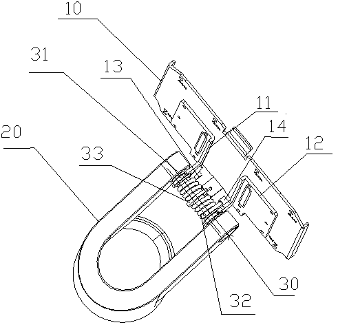
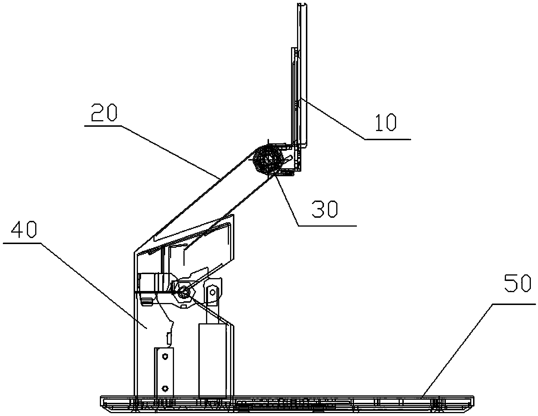
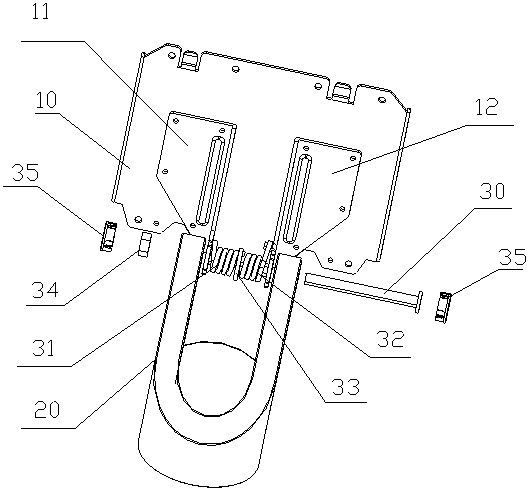
[0019] see Figure 1 to Figure 3 In this embodiment, the rotating shaft structure for the folding stand of the display includes a display fixing plate 10 , fixing feet, lifting die castings 20 , a support frame 40 and a base 50 . The upper end of the lifting die-casting part 20 is connected to the fixed foot through the shaft core 30 , and its lower end is movably connected to the upper end of the support frame 40 , and the bottom end of the support frame 40 is fixed on the base 50 . The fixing legs of this embodiment include a left leg 11 and a right leg 12 , both of which are fixed on the display fixing plate 10 .

[0020] A forward torsion spring 32 and a reverse torsion spring 31 are installed on the two ends of the shaft c...


PUM


Abstract

The invention discloses a rotating shaft structure for a display folding bracket, which comprises fixed support legs and a lifting die casting, wherein the lifting die casting is connected with the fixed support legs through a central spindle which is provided with a positive torsional spring and a negative torsional spring, a torsional gasket fixed on the central spindle is arranged between the positive torsional spring and the negative torsional spring, one ends of the positive torsional spring and the negative torsional spring are respectively fixed on the torsional gasket, and a positive baffle member used for baffling the other end of the positive torsional spring and a negative baffle member used for baffling the other end of the negative torsional spring are arranged on the fixed support legs. The positive torsion spring and the negative torsional spring are arranged on the first central spindle, the rotating shaft structure provided by the invention ensures that a display fixing plate has stable and reliable elasticity within an angle rotating range and is light in rotation and simple in operation so that the service life of the central spindle is prolonged, thereby being light and free in operation, being stable and reliable, ensuring the installation use range of a display, furthest meeting the seeing and hearing demands and meeting the angle requirements of watching the display.

Description

technical field [0001] The invention relates to a rotating shaft structure, in particular to a rotating shaft structure for a display folding stand. Background technique [0002] An all-in-one computer refers to the integration of the host computer of a traditional split desktop into a monitor to form an all-in-one desktop. With the development of the times, technology and market, more and more manufacturers have begun to set foot in this field; the all-in-one machine has strong vitality and is gradually being sought after by people. Compared with traditional desktop computers, the design of all-in-one computers is more in line with the urban living environment and the aesthetic needs of modern people. Compared with traditional desktop computers, it has incomparable advantages of convenience. It has found the balance point that best suits consumers' aesthetic concepts in terms of volume and appearance. As a support frame, it is an inseparable combination of computer integra...

Claims


Application Information

Patent Timeline
Patent Type & Authority Patents(China)
IPC IPC(8): F16C11/12F16M11/06F16M11/38
Inventor 夏勇曲波陈春
Owner TAIZHOU STRONKIN ELECTRONICS
Why Eureka
Try Eureka