
Method for repairing cavities of monitoring area with mobile nodes

A technology for monitoring areas and mobile nodes, applied in electrical components, wireless communication, network topology, etc., can solve problems such as inability to obtain optimal solutions, expensive sensor nodes, and difficulty in finding accurate solutions

Inactive Publication Date: 2012-02-22
SUZHOU UNIV
View PDF1 Cites 19 Cited by
  • Summary
  • Abstract
  • Description
  • Claims
  • Application Information

AI Technical Summary

Problems solved by technology

The use of geographic information makes the processing very simple, but the acquisition of geographic information requires the support of devices such as GPS, which is very expensive for large-scale deployment of sensor nodes
In addition, for the hole repair problem, it is also an N-P problem, and it is difficult to find an accurate solution. Using geographic information is only a little more accurate to solve the problem, but it still cannot get the optimal solution.

Method used

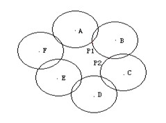
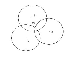
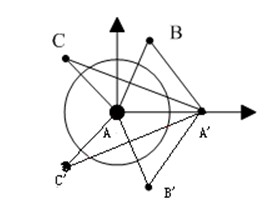

Image

  • Method for repairing cavities of monitoring area with mobile nodes
  • Method for repairing cavities of monitoring area with mobile nodes
  • Method for repairing cavities of monitoring area with mobile nodes

Examples


Embodiment 1

[0053] The method is distributed and it is divided into two parts, hole detection and hole repair. When a node is checked as fully covered by hole detection, it will not execute subsequent parts, otherwise the hole repair process is performed.

[0054] First, some assumptions and terms mentioned in the method of this embodiment:

[0055] Assuming that each node has a unique identification number, the node can perceive a certain area and communicate with adjacent nodes. Its sensing and communication range is assumed to be a circle with a fixed radius, respectively SR and TR, and TR≥2SR. In addition, there is no precise geographical information, but the nodes in the border area can correctly identify themselves, and the border of the monitoring area will not be misjudged as a hollow area.

[0056] The present invention has no specific requirements on whether the cavity is closed. At the same time, it is assumed that each node has a certain mobility. Through the limited movemen...


PUM


Abstract

The invention discloses a method for repairing cavities of a monitoring area with mobile nodes. The method comprises the following steps of: detecting the cavities at first; determining the position information of adjacent nodes in a wireless sensing network in a manner of moving one node for two times; removing generated pseudo interior points by using the property of a covered arc, determining an optimal mobile interior point; and finally, calculating the distance from the interior point to a node at the edge of the cavity, and moving the node at the edge of the cavity to the optimal position. When the cavities are distributed densely, the good cavity repairing property can be obtained through a shorter mobile distance.

Description

technical field [0001] The invention relates to a method for arranging a wireless sensor network, in particular to a method for repairing holes in a wireless sensor grid in a monitoring area based on a mobile node. Background technique [0002] The wireless sensor network is formed by deploying a large number of low-cost sensor nodes to the target area. These nodes have the functions of sensing and computing the surrounding environment. At the same time, the nodes can communicate with each other. They can be widely used in military, transportation, medical treatment, disaster relief, etc. field. With the continuous development of electronic technology, the functions of sensor nodes are continuously enhanced and the volume is continuously reduced, making it possible to deploy sensor nodes on a large scale to monitor a certain area. However, the randomly deployed sensor nodes may not cover the entire area, thus forming some areas called "holes" that are not perceived by the n...

Claims


Application Information

Patent Timeline
IPC IPC(8): H04W16/18H04W24/00H04W64/00H04W84/18
Inventor 张书奎樊建席杨凯王进
Owner SUZHOU UNIV
Learn More