
Deceleration device

A technology of reduction gear and components, which is applied in the direction of transmission, transmission parts, gear transmission, etc., can solve the problems of limitation of movable range, lower degree of freedom of reduction ratio, limitation of movement range, etc., to achieve the effect of ensuring degree of freedom

Active Publication Date: 2012-03-14
SUMITOMO HEAVY IND LTD
View PDF4 Cites 4 Cited by
  • Summary
  • Abstract
  • Description
  • Claims
  • Application Information

AI Technical Summary

Problems solved by technology

At this time, the movable range of the first and second pin members 5A, 6A relative to the pin holes 2A, 3A is limited, and the swingable motion range of the external gears 2, 3 is limited.
As a result, the speed reducer 1 is difficult to perform speed reduction with a low reduction ratio requiring a wide swing range, and becomes a speed reducer that can only perform speed reduction with a high speed reduction ratio that can be realized within a narrow swing range, resulting in a change in the degree of freedom of the speed reduction ratio. Low

Method used


Image

  • Deceleration device
  • Deceleration device
  • Deceleration device

Examples


Embodiment Construction

[0022] Hereinafter, an example of embodiment of the present invention will be described with reference to the drawings.

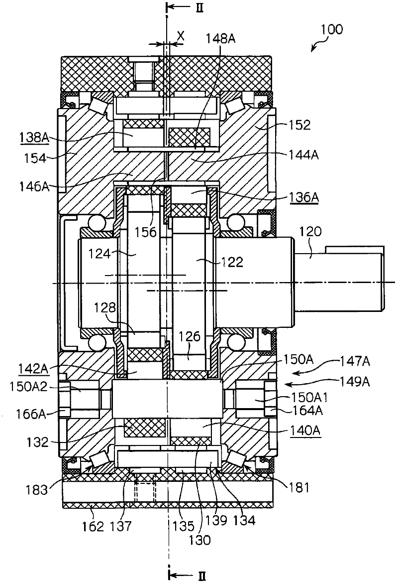
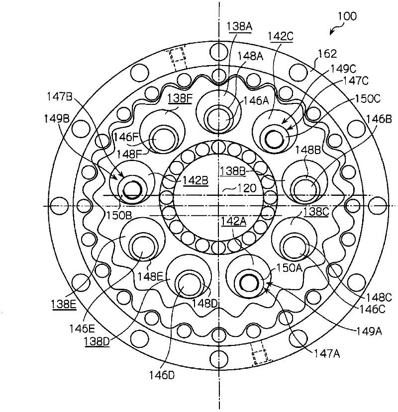
[0023] figure 1 A longitudinal sectional view of the reduction gear transmission 100 is shown in . and, figure 2 shown along the figure 1 The sectional view of the II-II line indicated by the arrow II.

[0024] First, if the basic situation will be described, the reduction gear transmission 100 according to this embodiment is characterized in that it includes: first and second external gears 130 and 132; an internal gear 134; and the first and second external gears 130 , 132 internal meshing; the first and second flange bodies 152 and 154 are arranged oppositely on both axial sides of the first and second external gears 130 and 132; and a plurality (six in this example) of the first 1 pin parts 144A~144F ( figure 1 In the illustrated example, only 144A) and the second pin members 146A to 146F are shown. The first and second pin members 144A to 144...


PUM


Abstract

The invention provides a deceleration device capable of guaranteeing the free degree of a reduction ratio of the deceleration device, and realizing a miniaturization. The deceleration device comprises outer gears(130, 132), an inner gear(134) meshed with the outer gears(130, 132), first and second flange bodies(152, 154) configurated at the axial two sides of the outer gears(130, 132), and first and second pin parts(144A-144F, 146A-146F) protruded towards the axial directions respectively from the opposite sides of the first and second flange bodies(152, 154), penetrating the outer gears(130, 132), and synchronized with the self-rotation components of the outer gears(130, 132); wherein, the first flange body(152) and the second flange body(154) are not connected at the positions of the first and second pin parts(144A-144F, 146A-146F) along the axial directions, while are connected along the axial directions beyond the positions of the first and second pin parts(144A-144F, 146A-146F).

Description

technical field [0001] The invention relates to a reduction gear. Background technique [0002] Disclosed in Patent Document 1 as Figure 6 The reduction gear shown. [0003] The reduction gear 1 has: external gears 2, 3; internal gear 4, internally meshing with the external gears 2, 3; first and second flange bodies 5, 6, arranged on both axial sides of the external gears 2, 3; And the first and second pin members 5A, 6A. The first and second pin members 5A and 6A protrude in the axial direction from the first and second flange bodies 5 and 6 respectively, and penetrate through the pin holes 2A and 3A of the external gears 2 and 3 . A plurality of first and second pin members 5A, 6A are provided along the circumferential direction of the reduction gear transmission 1 (in this example, only two are shown). Bolts 7 and 8 are inserted through the first and second flange bodies 5 and 6 and all the first and second pin members 5A and 6A, and the first flange body 5 and the se...

Claims


Application Information

Patent Timeline
IPC IPC(8): F16H1/32F16H57/021
CPCF16H1/32F16H2001/325F16H1/28
Inventor 山本章
Owner SUMITOMO HEAVY IND LTD
Learn More