Method and system for dynamic reactive power compensation

A dynamic and phase-separation technology, applied in the dynamic reactive power compensation system and the field of dynamic reactive power compensation, can solve the problems of poor control continuity, large volume, poor dynamic performance, etc., and achieve large compensation capacity, high quality and control flexibility strong effect

Active Publication Date: 2016-03-23
EAST CHINA ELECTRIC POWER TEST & RES INST +1
View PDF3 Cites 0 Cited by
  • Summary
  • Abstract
  • Description
  • Claims
  • Application Information

AI Technical Summary

Problems solved by technology

[0005] Another technical problem to be solved by the present invention is to provide a dynamic reactive power compensation system, which can solve the problems of poor dynamic performance, bulky volume, limited capacity, poor control continuity and low power quality of existing reactive power compensation equipment. Make reactive power compensation more intelligent, small and efficient, and effectively improve the power quality of power grid power supply

Method used


Image

  • Method and system for dynamic reactive power compensation

Examples


Embodiment Construction

[0027] In order to make the purpose and features of the present invention more comprehensible, the specific implementation manners of the present invention will be further described below in conjunction with the accompanying drawings.

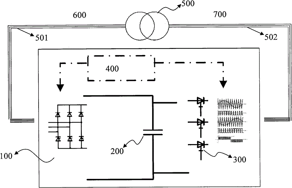
[0028] For details, please refer to figure 1 , the dynamic reactive power compensation system disclosed in the present invention includes:

[0029] a controllable reversible rectifier 100 for storing the required energy from the high voltage level grid 600 on the energy storage medium 200;

[0030] The energy storage medium 200 is connected with the controllable reversible rectifier 100, and is used for storing energy from the high-voltage power grid 600;

[0031] A controllable phase-splitting inverter 300, connected to the energy storage medium 200, for transferring energy from the energy storage medium 200 to the low-voltage power grid 700;

[0032] The controller 400 is connected with the controllable reversible rectifier 100 and the cont...


PUM


Abstract

The invention discloses a dynamic reactive power compensation method, which comprises the following steps that: (1) a controlled reversible rectifier stores required energy onto an energy storage medium from a high-voltage power grid; (3) a controlled split-phase inverter delivers the energy from the energy storage medium to a low-voltage power grid; and (3) a controller controls the controlled reversible rectifier and the controlled split-phase inverter to make the low-voltage power grid obtain reactive power compensation. The invention also discloses a system based on the method. The system comprises the controlled reversible rectifier, the energy storage medium, the controlled split-phase inverter and the controller. By the method and the system, the problems of huge volume, finite capacity, low regulation and control continuity and low electric power quality of reactive power compensation equipment are solved.

Description

technical field [0001] The invention relates to a technical method of reactive power control in the field of power grid, in particular to a method of dynamic reactive power compensation. The present invention also relates to a dynamic reactive power compensation system based on the above method. Background technique [0002] At present, in substations and large user-side power grids, capacitor / reactor switching is generally used to solve the problem of reactive power compensation. In some stations, static dynamic var compensation devices (SVC) and static var generators (SVG) are used. , Static synchronous compensator (STATCOM) and other relatively advanced reactive power compensation equipment. But these devices all have a common problem: limited reactive power compensation capacity, poor control continuity, and low power quality! Facing the ever-growing power grid and users with higher standards, we can only continuously increase equipment investment, but it is still diff...

Claims


Application Information

Patent Timeline
Patent Type & Authority Patents(China)
IPC IPC(8): H02J3/18
CPCY02E40/30
Inventor 张健赵海生
Owner EAST CHINA ELECTRIC POWER TEST & RES INST
Why Eureka
Try Eureka