Electrostatic discharge protecting device and method thereof

An electrostatic discharge protection, power supply voltage technology, applied in emergency protection circuit devices, circuit devices, emergency protection circuit devices for limiting overcurrent/overvoltage, etc., can solve the problem that general products and methods have no suitable structure and method, Inconvenience, affecting the operation of internal circuits, etc.

Active Publication Date: 2012-03-21
MACRONIX INT CO LTD
View PDF5 Cites 4 Cited by
  • Summary
  • Abstract
  • Description
  • Claims
  • Application Information

AI Technical Summary

Problems solved by technology

However, the holding voltage of the discharge path provided by this architecture is usually less than 10.5 volts
Therefore, when the internal circuit is operating, electrical overstress (EOS) events often occur continuously due to the holding voltage being too low, thereby affecting the operation of the internal circuit.
[0004] It can be seen that the above-mentioned existing electrostatic discharge protection device and method obviously still have inconvenienc

Method used


Image

  • Electrostatic discharge protecting device and method thereof
  • Electrostatic discharge protecting device and method thereof
  • Electrostatic discharge protecting device and method thereof

Examples


no. 1 example

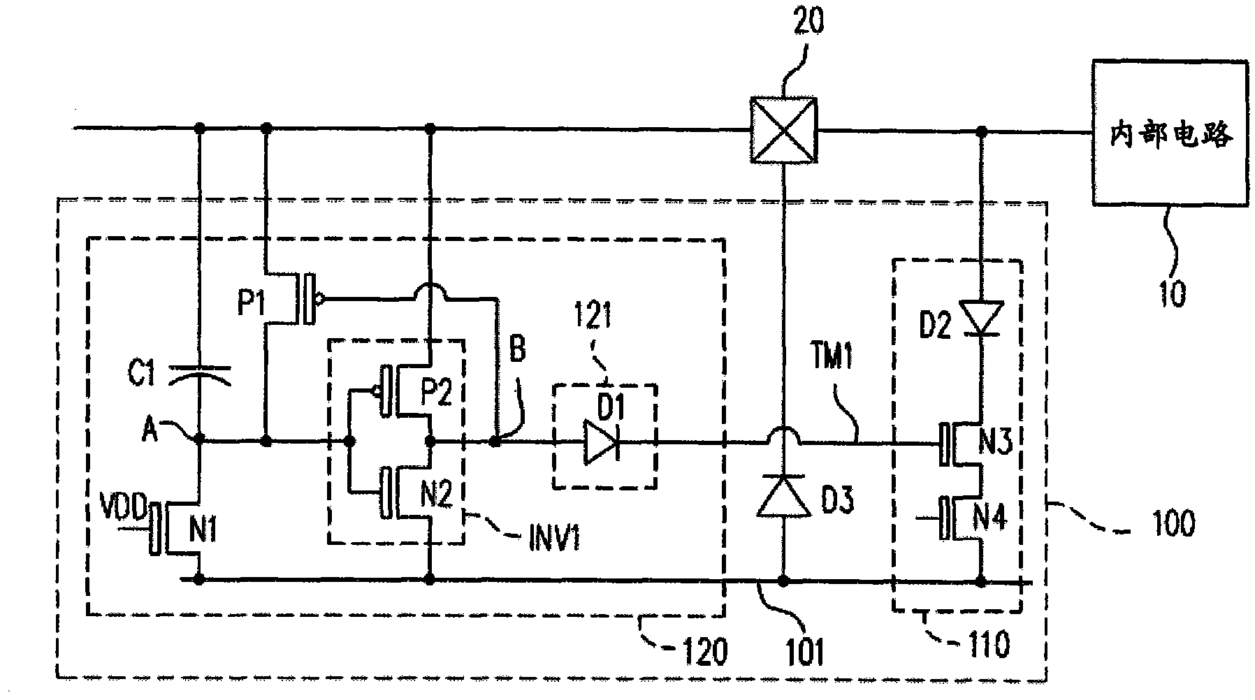
[0058] figure 1 is a schematic structural view of the electrostatic discharge protection device according to the first embodiment of the present invention, wherein figure 1 The internal circuit 10 and the bonding pad 20 are also shown. see figure 1 As shown, the internal circuit 10 operates at a power supply voltage VDD and receives an input voltage through the bonding pad 20 . In addition, the ESD protection device 100 is used to protect the internal circuit 10 to avoid damage to the internal circuit 10 caused by an electrostatic signal.

[0059] The ESD protection device 100 includes a protection unit 110 and a control unit 120 . Further, the protection unit 110 includes a diode D2, an N-type transistor N3, and an N-type transistor N4. Wherein, the anode end of the diode D2 is electrically connected to the pad 20 and the internal circuit 10 . The drain terminal of the N-type transistor N3 is electrically connected to the cathode terminal of the diode D2 , and the gate t...

no. 2 example

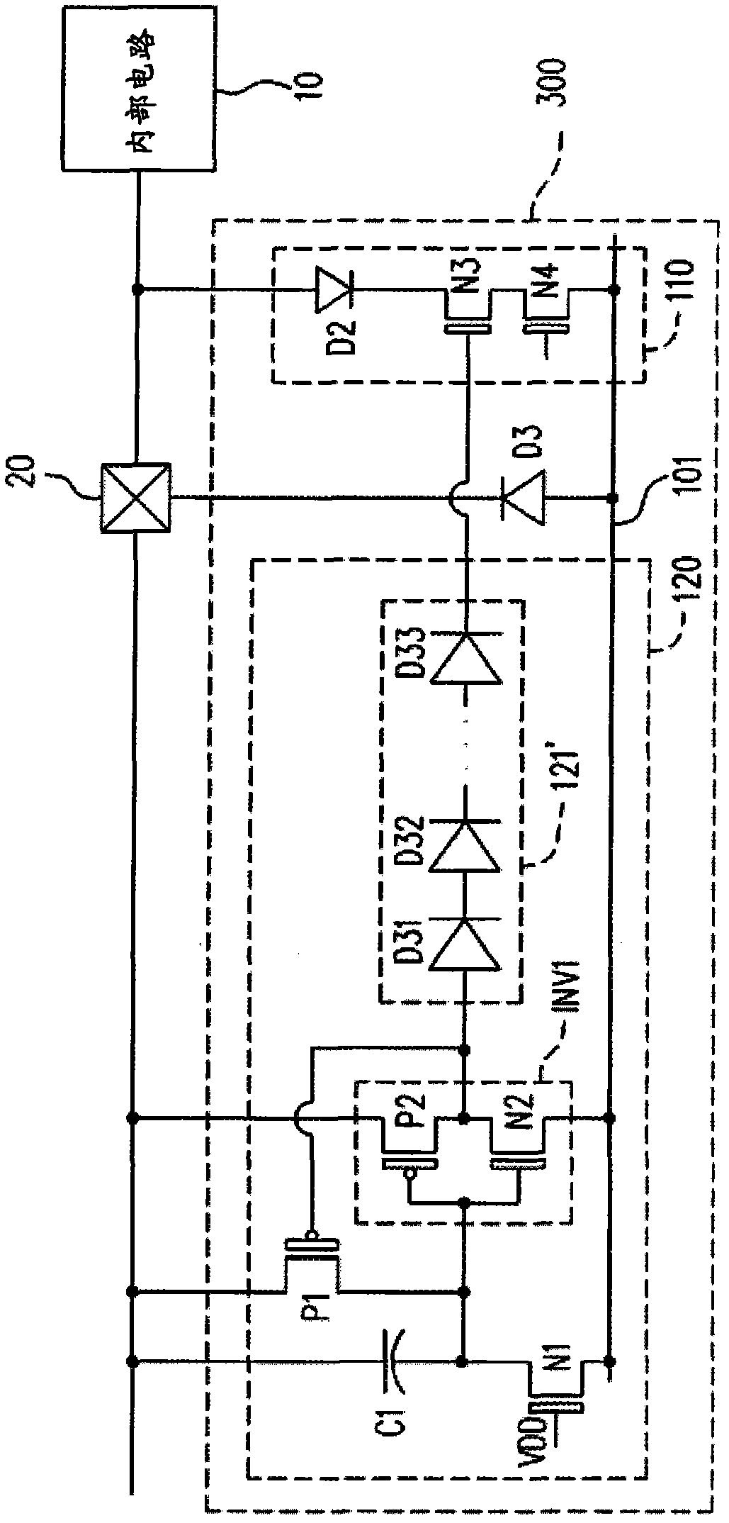
[0072] image 3 is a schematic structural diagram of an electrostatic discharge protection device according to a second embodiment of the present invention. see image 3 As shown, this embodiment is substantially the same as the first embodiment, and image 3 The same or similar component numbers represent the same or similar components, and will not be repeated in this embodiment.

[0073] The main difference between this embodiment and the first embodiment is that in the ESD protection device 300 described in this embodiment, the isolation circuit 121' is composed of a plurality of diodes D31-D33. Wherein, the diodes D31 - D33 are connected in series to form a diode series. In addition, the anode end of the diode series, that is, the anode end of the diode D31, is used as the first end of the isolation circuit 121', and the cathode end of the diode series, that is, the cathode end of the diode D33, is used as the isolation circuit 121' of the second end. In this way, wh...

no. 3 example

[0075] Figure 4 is a schematic structural diagram of an electrostatic discharge protection device according to a third embodiment of the present invention. see Figure 4 As shown, this embodiment is substantially the same as the first embodiment, and Figure 4 The same or similar component numbers represent the same or similar components, and will not be repeated in this embodiment.

[0076] The main difference between this embodiment and the first embodiment is that: in the electrostatic discharge protection device 400 described in this embodiment, the isolation circuit 121 "is composed of an N-type transistor N5. Wherein, the N-type transistor N5 The gate terminal is electrically connected to the drain terminal to form the first terminal of the isolation circuit 121", and the source terminal of the N-type transistor N5 is used as the second terminal of the isolation circuit 121". In this way, when the isolation circuit 121" is the first terminal When the voltage level of...


PUM


Abstract

The invention provides an electrostatic discharge protecting device and an electrostatic discharge protecting method. The electrostatic discharge protecting device is used for protecting an inner circuit which is operated under a supply voltage. The electrostatic discharge protecting device comprises a protecting unit and a controlling unit. The protecting unit is used for providing a discharge path so as to conduct an electrostatic signal from a bonding pad to an earth lead. The protecting unit is used for adjusting a holding voltage and a trigger voltage which decide whether the discharge path is conducted according to the voltage level of a control end of the protecting unit. When the supply voltage is supplied, the control unit is used for conducting an input voltage into a control end of the protecting unit, so that the holding voltage and the trigger voltage of the discharge path are improved by the protecting unit. When the supply voltage is not supplied, the control unit is used for switching a control end of the protecting unit to be a suspension joint status by the electrostatic signal, so that the holding voltage and the trigger voltage of the discharge path are reduced by the protecting unit.

Description

technical field [0001] The present invention relates to an electrostatic discharge protection device and method, in particular to an electrostatic discharge protection device and method capable of adjusting holding voltage and trigger voltage related to a discharge path. Background technique [0002] Electrostatic discharge (ESD) is the phenomenon of the movement of static electricity from non-conductive surfaces, which can cause damage to semiconductors and other circuit components in integrated circuits. For example, when a human body walking on a carpet, a machine packaging an integrated circuit, or an instrument for testing an integrated circuit touches a chip, it will discharge to the chip. The instantaneous power of this electrostatic discharge may cause damage to the chip. The integrated circuit is damaged or fails. [0003] In order to prevent integrated circuits from being damaged due to electrostatic discharge phenomena, electrostatic discharge protection devices ...

Claims


Application Information

Patent Timeline
IPC IPC(8): H02H9/04H01L23/60
Inventor 王世钰陈彦宇刘玉莲
Owner MACRONIX INT CO LTD
Why Eureka
Try Eureka