Permanent magnet synchronous motor and U-shaped rotor structure thereof

A permanent magnet synchronous motor and rotor structure technology, which is applied in the direction of synchronous machine, magnetic circuit shape/style/structure, magnetic circuit rotating parts, etc., can solve the problem of affecting the strength of the magnetic isolation bridge, poor workmanship, and failure to meet the electromagnetic performance requirements of the motor and other issues to achieve the best electromagnetic performance and ensure reliability

Inactive Publication Date: 2012-03-21
CSR ZHUZHOU ELECTRIC CO LTD
View PDF5 Cites 1 Cited by
  • Summary
  • Abstract
  • Description
  • Claims
  • Application Information

AI Technical Summary

Problems solved by technology

[0004] However, the existing rotor structure has the following technical problems: the centrifugal force caused by the mass of the permanent magnet and the rotor core itself will act on the magnetic isolation bridge, and the magnetic isolation bridge needs to bear relatively large pressure, which affects the strength of the magnetic isolation bridge , and thus cannot meet the electromagnetic performance requirements of the motor, and the rotor structure of the traditional structure also has problems such as poor manufacturability and low installation efficiency of permanent magnets.
Especially when the power of the motor is large, such as above 100kW, and the speed is also high, such as the permanent magnet synchronous motor application field above 1000r / min, such as the permanent magnet direct drive field of the central air-conditioning compressor, the centrifugal force of the permanent magnet and the rotor core has an effect on the isolation The influence of the magnetic bridge is more obvious, and it is more difficult to meet the requirements with the traditional rotor magnetic circuit structure

Method used


Image

  • Permanent magnet synchronous motor and U-shaped rotor structure thereof
  • Permanent magnet synchronous motor and U-shaped rotor structure thereof

Examples


Embodiment Construction

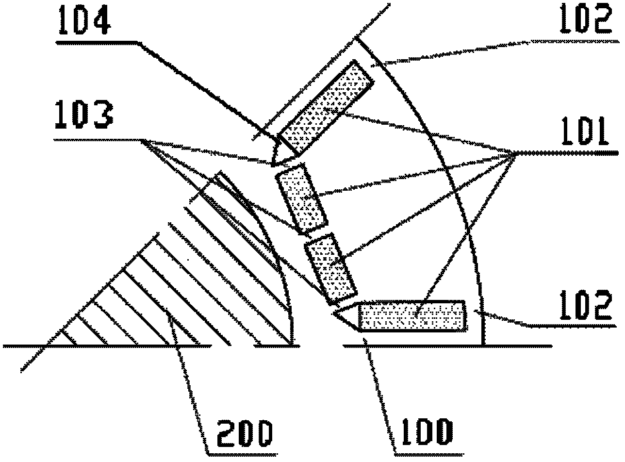
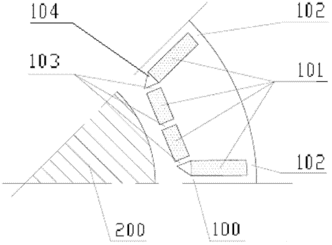
[0016] The core of the present invention is to provide a U-shaped rotor structure of a permanent magnet synchronous motor. The number of permanent magnets in each pole of the rotor structure is at least three, and there are reinforcing ribs between the permanent magnets, so that the rotor core and the permanent magnets The influence of centrifugal force on the magnetic isolation bridge is reduced. Another core of the present invention is to provide a permanent magnet synchronous motor including a rotor structure.

[0017] In order to enable those skilled in the art to better understand the technical solution of the present invention, the present invention will be further described in detail below in conjunction with the accompanying drawings and specific embodiments.

[0018] Please refer to figure 1 , figure 1 It is a structural schematic diagram of a specific embodiment of the U-shaped rotor structure of the permanent magnet synchronous motor proposed in the present invent...


PUM


Abstract

The invention discloses a permanent magnet synchronous motor and a U-shaped rotor structure thereof, and discloses the U-shaped rotor structure provided with a rotor core, at least three permanent magnets and a magnetism isolating bridge are respectively arranged on each pole of the rotor core, mounting holes with the number corresponding to the permanent magnets, which are used for mounting the permanent magnets, are formed on the rotor core, and a rotor core part between every two mounting holes forms a strengthening rib; the permanent magnets in each pole are in U-shaped arrangement; and the opening of the shape of the letter U faces to the outer edge of the rotor core. The strengthening ribs are arranged between the permanent magnets of each pole of the rotor structure, the mass of the rotor core and the centrifugal force produced by the mass of the permanent magnet can be borne by the strengthening ribs, so that influences caused by the centrifugal force to the intensity of the magnetism isolating bridge can be reduced; and the strengthening ribs have a good magnetism isolating effect.

Description

technical field [0001] The invention relates to the technical field of motors, in particular to a permanent magnet synchronous motor and a U-shaped rotor structure thereof. Background technique [0002] With the gradual maturity of the development and control technology of permanent magnet synchronous motors, and the continuous development of permanent magnets in terms of performance and industrialization, there is increasing interest and demand for permanent magnet synchronous motors in various fields, especially permanent magnet synchronous variable frequency speed control motors. bigger. At present, permanent magnet synchronous motors are widely used in various servo motors, wind power generation fields, oil drilling and electric vehicle drive motors, etc. [0003] The permanent magnet synchronous motor includes a stator structure, a rotor structure and a rotating shaft, and the rotating shaft drives the rotor structure to rotate. Each pole of the rotor core is equipped...

Claims


Application Information

Patent Timeline
Patent Type & Authority Applications(China)
IPC IPC(8): H02K1/27H02K21/00
Inventor 晏才松周黎民张蕾刘方年杨云峰
Owner CSR ZHUZHOU ELECTRIC CO LTD
Why Eureka
Try Eureka