
Wide band amplifier with frequency compensation

A technology of frequency compensation and amplifier, which is applied in the field of wireless radio frequency communication, can solve the problems of difficult adjustment of the output level of the output terminal of the broadband amplifier, high bandwidth and increased power consumption, etc., so as to save power consumption, solve the problem of gain and Output level, effect of reducing parasitic capacitance

Active Publication Date: 2014-07-16
杭州中科微电子有限公司
View PDF4 Cites 0 Cited by
  • Summary
  • Abstract
  • Description
  • Claims
  • Application Information

AI Technical Summary

Problems solved by technology

The frequency of the intermediate frequency is relatively high, and a broadband amplifier circuit is required. When a common structure is used, more power consumption will be consumed, and the bandwidth is not easy to make very high.
The amplifier unit in the automatic gain control circuit of the subsequent stage also works under the same bandwidth, and the power consumption will be greater at this time
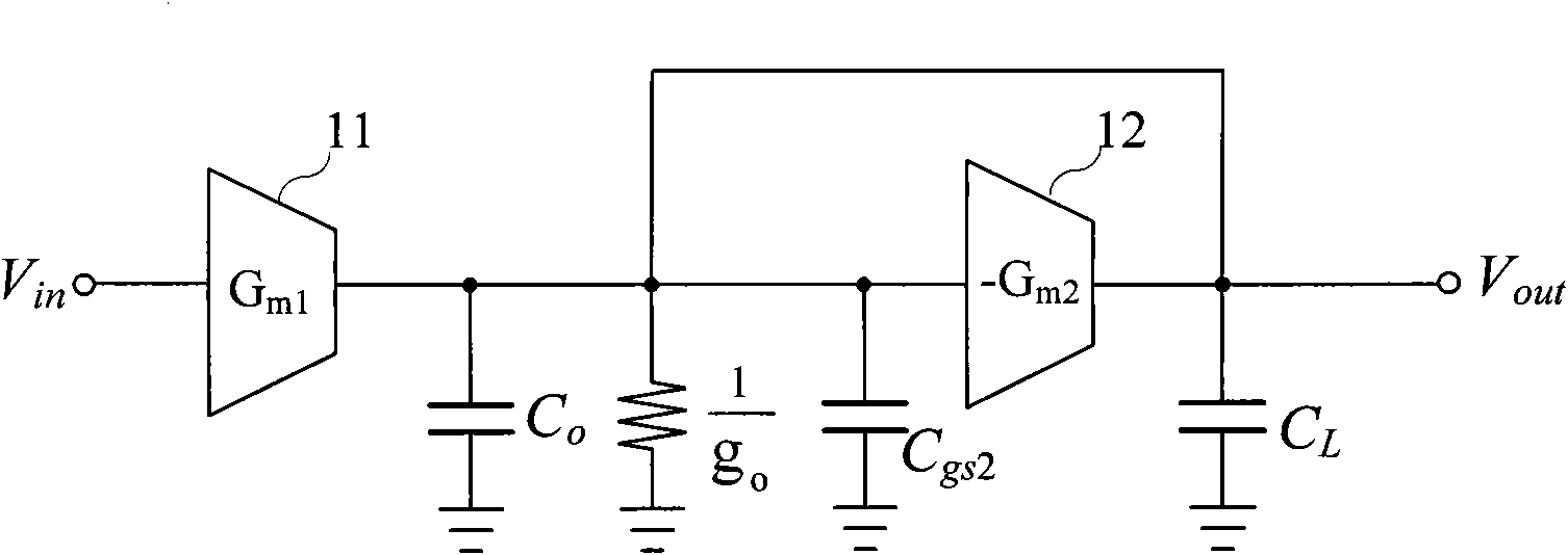
[0003] In the design of the current broadband amplifier, especially the amplifier unit of the automatic gain control circuit, in order to achieve high frequency characteristics, resistors are used as loads. This circuit structure can reduce parasitic capacitance, but the output level of the output terminal of the broadband amplifier is usually not easy to adjust. , there is a contradiction between gain and output level
It has been proposed in the literature to use active resistors as loads to achieve high frequency characteristics. Although it can solve the contradiction between gain and output level, the parasitic capacitance introduced by active loads will reduce the bandwidth. When working at higher frequencies , will also increase power consumption

Method used


Image

  • Wide band amplifier with frequency compensation
  • Wide band amplifier with frequency compensation
  • Wide band amplifier with frequency compensation

Examples


no. 1 example

[0070] Figure 5a An implementation form of a broadband amplifier circuit in which the frequency compensation resistor is an active resistive element is given. The first transconductance amplifier module 51 adopts a source-level negative feedback transconductance structure to improve linearity and have a good suppression effect on common-mode signals. The second transconductance module 52 is an active load module, which adopts a pseudo-differential transconductance equivalent output resistance structure to improve the linearity of the load resistance, and at the same time allow the output common mode level to be directly coupled with the input stage of the subsequent circuit.

[0071] The first transconductance amplifier module 51 is composed of an input stage, a bias circuit, a tail current source, and a load current source. MOS tubes M5 and M6 form the tail current source; MOS tubes M1 and M2 form the differential input stage; MOS tubes M3 and M4 form the load current sourc...

Embodiment

[0074] Figure 5b Another implementation form of a broadband amplifier circuit in which the compensation resistor is a channel mask resistor is given. Amplifier circuit implementations in the form of Figure 5a The implementation form of the amplifier circuit is basically the same, and the two frequency compensation resistors R C+ and R C- It is a channel mask resistor, the process is simpler to realize, and the resistance value of the resistance element is adjusted by design during realization.

no. 3 example

[0076] The electrical schematic diagram of another embodiment of the broadband amplifier circuit using the frequency compensation technology proposed by the present invention is as follows Figure 6 as shown, Figure 6 A third embodiment of another implementation form of a broadband amplifier circuit with a different structure is given. The first transconductance amplifier module 61 adopts a classic fully differential transconductance amplifier structure with a tail current source, which saves power consumption and has a good suppression effect on common-mode signals. The second transconductance module 62 is an active load module, which adopts the same fully differential transconductance amplifier structure with a tail current source as the first transconductance amplifier module, which is equivalent to a load at the output end and saves power consumption. When the circuit with this structure is used, a common-mode feedback circuit (CMFB) needs to be used to stabilize the com...


PUM


Abstract

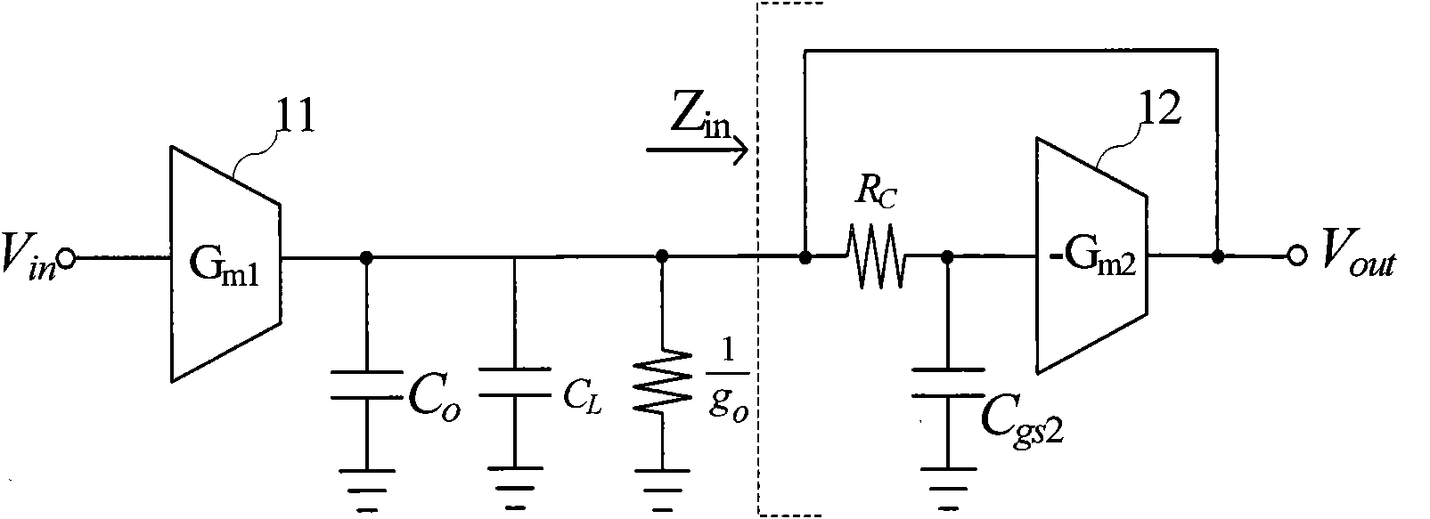
The invention provides a wide band amplifier with frequency compensation, wherein the working frequency range of a circuit of the amplifier can be expanded by means of frequency compensation. The wide band amplifier has a structure of an input / output circuit, wherein the circuit structure comprises a first transconductance amplifying unit, a second transconductance unit equivalent to a load circuit, two frequency compensation resistors embedded to a feedback loop of the second transconductance unit, and two capacitors equivalent to the load introduced by a post-stage circuit. The first transconductance amplifying unit has a structure of an input / output circuit, and is connected in series with the second transconductance unit of the feedback circuit structure. Two frequency compensation resistors are respectively matched with a parasitic input resistor at corresponding input end of the second transconductance unit to form a capacitance-resistance low-pass filter circuit by which a zero point is introduced in a transmission function of the wide band amplifier to expand the frequency working range of the wide band amplifier under the effect of the loop feedback. The wide band amplifier provided by the invention is used as the base amplifier unit applied to a radio frequency simulating front end of a receiver so as to achieve amplifying of an intermediate frequency signal. The wide band amplifier can also be applied to other systems to achieve amplification of a broadband.

Description

technical field [0001] The invention belongs to the technical field of wireless radio frequency communication and relates to a broadband amplifier, in particular to a frequency compensated broadband amplifier, which is applied to a CMOS radio frequency integrated receiver circuit and used to realize the amplification of intermediate frequency signals. Background technique [0002] In the CMOS RF integrated receiver circuit, after the RF signal is amplified by RF, it is down-converted to an intermediate frequency signal. The selection of the intermediate frequency frequency is related to the system architecture, ranging from a few MHz to dozens of MHz. The down-converted intermediate frequency signal is suppressed by the on-chip active filter, and then further amplified by the back-end automatic gain control circuit (AGC), and finally sent to the digital-to-analog converter (ADC) for quantization and encoding for digital baseband processing. In order to reduce the noise infl...

Claims


Application Information

Patent Timeline
Patent Type & Authority Patents(China)
IPC IPC(8): H03F1/42
Inventor 潘文光马成炎甘业兵于云丰王良坤
Owner 杭州中科微电子有限公司
Learn More