Bend molding die for automotive seat headrest pipe fittings

A car seat, bending forming technology, applied in the direction of forming tools, manufacturing tools, metal processing equipment, etc., can solve the problems of difficult processing, low processing efficiency, high cost, etc., and achieve the effect of convenient processing, high processing efficiency and low cost

Active Publication Date: 2012-04-04
中山邦塑精密塑胶有限公司
View PDF9 Cites 25 Cited by
  • Summary
  • Abstract
  • Description
  • Claims
  • Application Information

AI Technical Summary

Problems solved by technology

[0002] Car seat headrest pipe fittings generally have a U-shaped symmetrical structure, and the pipe body contains a continuous bending section structure, see figure 1 and figure 2 In the past, the bending and forming process o

Method used


Image

  • Bend molding die for automotive seat headrest pipe fittings
  • Bend molding die for automotive seat headrest pipe fittings
  • Bend molding die for automotive seat headrest pipe fittings

Examples


Embodiment Construction

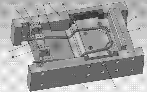
[0012] See image 3 , Figure 4 and Figure 5 , the present invention is a kind of bending forming mold of automobile seat headrest tube, which comprises upper mold structure and lower mold structure, upper mold structure includes upper mold plate 10, the upper part of upper mold plate 10 is connected with upper mold connecting plate 12 through upper pad iron 11 , the bottom is connected with the upper mold fixing plate 8 through the upper backing plate 9, the upper template 10 and the upper pad iron 11, the upper pad iron 11 and the upper mold connecting plate 12 are respectively connected by screws, the lower mold structure includes the lower template 1, the lower mold The bottom of the template 1 is equipped with a lower backing iron 32, the lower part of the upper mold fixing plate 8 is equipped with a forming punch structure, and the upper part of the lower template 1 is equipped with a forming die structure through the lower backing plate 3, and the forming punch struct...


PUM


Abstract

The invention provides a bend molding die for automotive seat headrest pipe fittings, which can one-step bend mold the pipe fittings with low process difficulty, high efficiency and low cost. It is comprised of an upper die structure and a lower die structure. The upper die structure includes an upper die plate, the upper part of the upper die plate being connected to the upper die junction platethrough an upper backup plate, the lower part of the upper die being connected to the upper die dead plate through an upper backup plate. The lower die structure includes a lower die plate, the lowerpart of the lower die plate being mounted with a lower backup plate, the lower part of the upper die dead plate being provided with a molding male die structure, the upper part of the lower die platebeing provided with a molding female die structure. The invention is characterized in that the molding male die structure comprises a molding male die and a pressure plate, the molding male die is fixed on the lower part of the upper die dead plate, the pressure plate is connected to the lower part of the upper die dead plate through an upper die unloading screw, a nitrogen cylinder is mounted onthe upper die junction plate, the mandrel of the nitrogen cylinder holds tightly against the upper part of the pressure plate after it drills through the upper die plate, the upper backup plate and the upper die dead plate; the molding female die structure comprises female die frame body, a molding female die and a locating structure, the molding female die being mounted within the female die frame body and facing the molding female die structure, the locating structure being positioned within the female die frame body and transversely two ends of the molding female die; the molding female die comprises a fixed female die and a movable female die, the molding male die and the movable female die are provided with bend molding grooves which cooperate; the fixed female die is fixed on the lower backup plate, the movable female die being mounted on the lower backup plate through the lower die unloading screw, and being held tightly by the lower mandrel.

Description

technical field [0001] The invention relates to the technical field of bending stamping die structure for pipe fittings, in particular to a bending forming die for headrest pipe fittings of automobile seats. Background technique [0002] Car seat headrest pipe fittings generally have a U-shaped symmetrical structure, and the pipe body contains a continuous bending section structure, see figure 1 and figure 2 In the past, the bending and forming process of the continuous bending section structure of such pipe fittings was mostly carried out by numerical control pipe bending machines. It needs to be equipped with corresponding fixtures, which is difficult to process, low in processing efficiency, and high in cost. Contents of the invention [0003] In view of the above problems, the present invention provides a bending mold for the pipe fitting of the headrest of an automobile seat, which can bend and shape the pipe fitting at one time, and has low processing difficulty, h...

Claims


Application Information

Patent Timeline
IPC IPC(8): B21D37/10B21D7/08
Inventor 周唯乐曹一枢黄健
Owner 中山邦塑精密塑胶有限公司
Why Eureka
Try Eureka