Method for polishing silicon through hole wafer and polishing combination for the same

A polishing composition and through-silicon via technology, applied in the field of polishing, can solve the problems of excessive difference in removal rate, decrease in silicon removal rate, increase in polishing rate of silicon and conductive materials, etc., and achieve reliable results

Active Publication Date: 2014-12-10
INTEGO
View PDF8 Cites 0 Cited by
  • Summary
  • Abstract
  • Description
  • Claims
  • Application Information

AI Technical Summary

Problems solved by technology

[0009] The above-mentioned various polishing compositions are all suitable for polishing a single specific material such as silicon or conductive materials. If silicon and conductive materials are polished at the same time, it is easy to have a large difference in the removal rate of the two materials. And it is difficult to simultaneously increase the polishing rate of silicon and conductive materials by increasing the content of specific components in the polishing composition; for example, when increasing the concentration of ethylenediamine in the polishing composition, the removal rate of silicon increases. The magnitude of the increase clearly exceeds the removal rate of conductive materials, that is, the removal rate of silicon may exceed However, the removal rate of conductive material may be only about
[0010] Similarly, it is known that the commonly used oxidizing agent H 2 o 2 The presence in the polishing composition helps to polish conductive materials, but it is easy to oxidize silicon into hard silicon dioxide, so when H in the polishing composition 2 o 2 The removal rate of the conductive material will also increase when the content of the silicon increases, but the removal rate of the silicon will decrease rapidly
[0011] From this point of view, H 2 o 2 Not suitable as a component in polishing compositions that polish both silicon and conductive materials

Method used


Image

  • Method for polishing silicon through hole wafer and polishing combination for the same
  • Method for polishing silicon through hole wafer and polishing combination for the same
  • Method for polishing silicon through hole wafer and polishing combination for the same

Examples


Embodiment Construction

[0024] The polishing method of the TSV wafer of the present invention includes polishing the surface of the TSV wafer with the above-mentioned polishing composition of the present invention. During the polishing process, the polishing composition flows to the polishing pad and the TSV wafer at a flow rate, while the TSV wafer is brought into contact with the polishing pad by applying a polishing pressure, and both have a rotational speed, so that the TSV wafer is in contact with the polishing pad. The TSV wafer is polished.

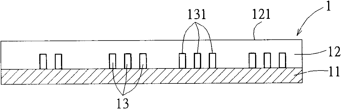
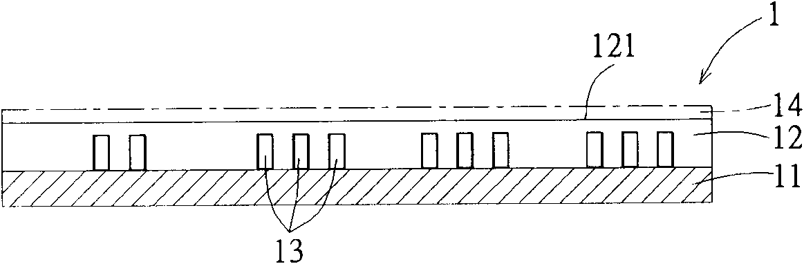
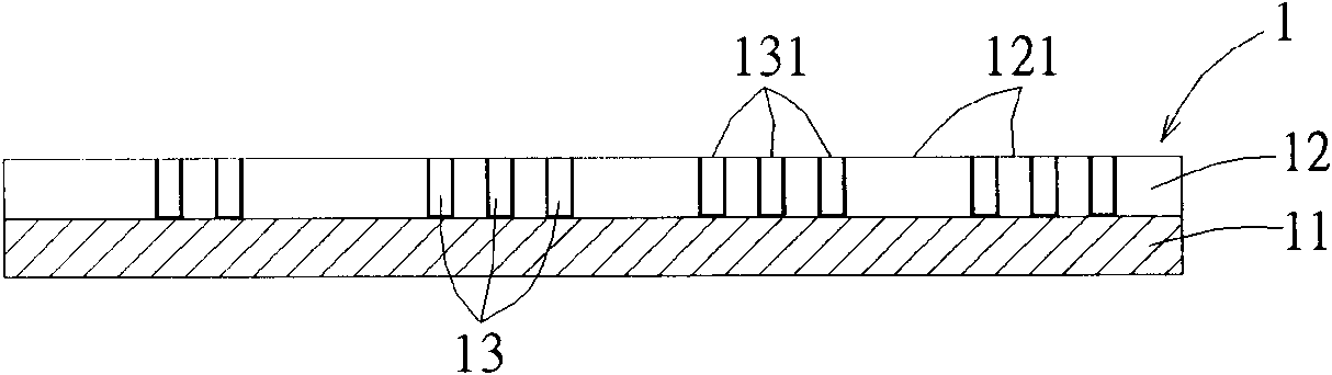
[0025] It must be explained that the above-mentioned "surface of the TSV wafer" means a surface of the TSV wafer away from the integrated circuit layer 11 thereof, which may be the surface 121 of the silicon wafer layer (eg figure 1 shown) or the top surface 131 (such as image 3 shown).

[0026] In this mode of operation, the removal rates of conductive material and silicon from TSV wafers can be achieved simultaneously above, even above, more or e...


PUM


Abstract

The invention relates to a method for polishing silicon through hole wafer and a polishing combination for the same. The method comprises the following steps of: using the polishing combination consisting of organic alkali compound, oxidant selected from sodium chlorite and / or potassium bromate, multiple silicon dioxide ground particles and solvent to polish the surface of the silicon through hole wafer so as to remove silicon and conductive material on the silicon through hole wafer by a removal rate respectively. By the method, the silicon and the conductive material on the silicon through hole wafer can be polished with higher polishing rate so as to greatly reduce time cost required for polishing the silicon through hole wafer. The invention also relates to the polishing combination used in the method.

Description

technical field [0001] The present invention relates to a polishing method, in particular to a polishing method of a Through-Silicon Via (TSV) wafer. The present invention also relates to polishing compositions used in carrying out the method. Background technique [0002] The original structure of TSV wafer 1 is as follows figure 1 As shown, it includes an integrated circuit layer 11, a silicon wafer layer 12 on the integrated circuit layer 11, and a plurality of surfaces 121 of the silicon wafer layer 12 embedded in and connected to the silicon wafer layer 12 substantially vertically. to the conductive material 13 of the integrated circuit layer 11 . Generally speaking, the end face 131 of the conductive material 13 in the unpolished TSV wafer is spaced from the surface 121 of the silicon wafer layer 12 by about several hundreds of microns. [0003] The surface 121 will then be polished in a "grinding" manner to rapidly thin the silicon wafer layer 12 to a distance betw...

Claims


Application Information

Patent Timeline
Patent Type & Authority Patents(China)
IPC IPC(8): H01L21/304C09G1/02
Inventor 李康华刘文政
Owner INTEGO
Why Eureka
Try Eureka