Check patentability & draft patents in minutes with Patsnap Eureka AI!

Electromagnetic Contactor

An electromagnetic contactor and connecting part technology, applied in electromagnetic relays, relays, electromagnetic relay detailed information and other directions, can solve the problems of insufficient wiring space, narrow interval, and difficulty in routing external wiring, and achieve easy wiring operations. Effect

Inactive Publication Date: 2012-04-11
FUJI ELECTRIC FA COMPONENTS & SYST CO LTD
View PDF7 Cites 2 Cited by
  • Summary
  • Abstract
  • Description
  • Claims
  • Application Information

AI Technical Summary

Problems solved by technology

[0008] However, the electromagnetic contactor 2 and thermal overload relay 3 connected to the load side main circuit terminals 2b1~2b3 and the power supply side connecting rods 3a1~3a3, the other side of the electromagnetic contactor 2 (load side auxiliary terminals 2b4 and load side The distance between the coil terminal 2b5 side) and the side of the thermal overload relay 3 is narrow ( Figure 8 The area marked with ○ in A) cannot ensure sufficient wiring space for connecting the load-side auxiliary terminal 2b4 and load-side coil terminal 2b5 with external wiring.
[0009] Therefore, in the case of connecting external wiring such as highly rigid insulation-coated wiring, the external wiring has to be bent in a narrow wiring space so that the wiring terminal at the front end is connected to the load-side auxiliary terminal 2b4 and the load-side coil terminal. Corresponding to 2b5, the routing of external wiring is more difficult
[0010] In addition, the intervals between the three-phase load-side main circuit terminals 2b1 to 2b3 of the electromagnetic contactor 2 and one side of the thermal overload relay 3 are also narrow and there is no sufficient wiring space. When any two of the circuit terminals 2b1~2b3 are connected to a single-phase power supply and two external wirings are connected, it is also difficult to route the external wiring.

Method used


Image

  • Electromagnetic Contactor
  • Electromagnetic Contactor
  • Electromagnetic Contactor

Examples


Embodiment Construction

[0071] Hereinafter, best modes for carrying out the present invention (hereinafter referred to as embodiments) will be described in detail with reference to the drawings. In the following embodiments, various limitations are given to constituent elements, types, combinations, shapes, relative arrangements, etc., but these are merely examples, and the present invention is not limited thereto. for with Figure 8 and Figure 9 Portions having the same structure are denoted by the same reference numerals, and explanations thereof are omitted.

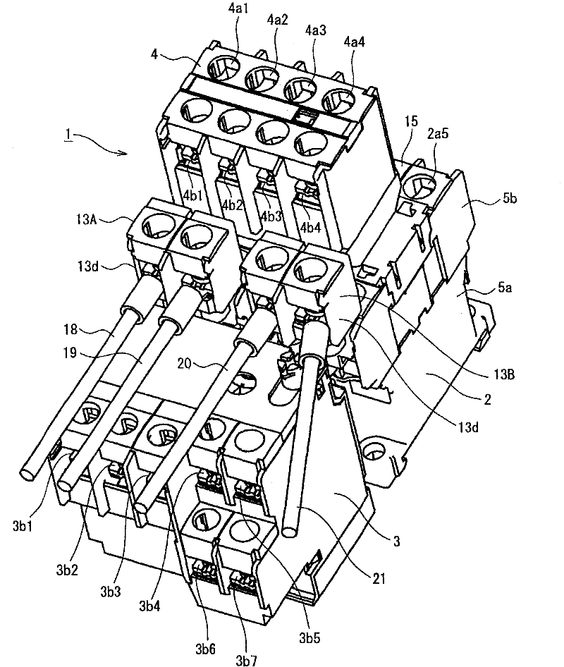
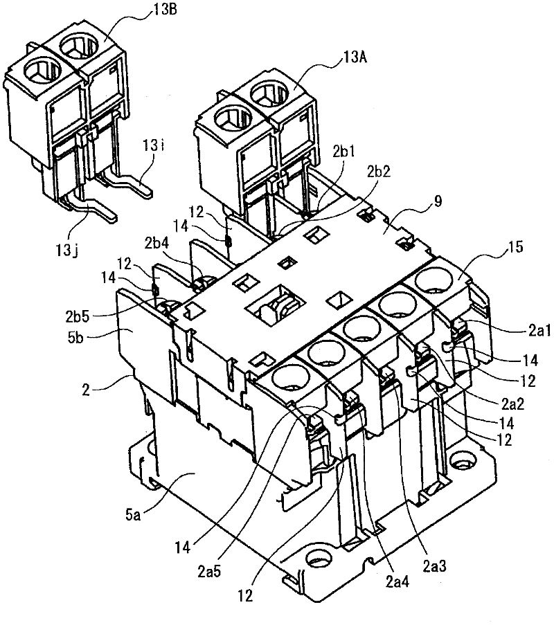
[0072] figure 1 It shows the electromagnetic switch 1 related to the present invention, the first relay terminal block 13A is connected to the load side main circuit terminals 2b1 and 2b2 on the other side of the electromagnetic contactor 2, and the second relay terminal block 13B is connected to the load side auxiliary terminal 2b4 is connected to the load side coil terminal 2b5.

[0073] The housing of the electromagnetic contactor 2 ...


PUM


Abstract

The invention provides an electromagnetic contactor capable of realizing external wire arrangement easily even terminals connecting with other units causing narrow space exist. In the invention, at least one among multiple load side terminals (2b1-2b5) arranged in array in a side part of a shell (5b) of a contactor body connects with a power source side connection part (3a1-3a3) of a thermal actuating overload relay (3). In the electromagnetic contactor having narrow space around the load side terminal caused by the proximate configuration of the thermal actuating overload relay, relay terminal components (13A, 13B) are arranged. The relay terminal components includes connection parts (13i, 13j) connecting with at least one of the multiple load side terminals; conductor leg parts (13g, 13h) going through the wire arrangement room near the side part form the connection part and standing vertically to an external side of the shell of the contactor body; and relay terminals (13p, 13q) arranged on the external side of the shell of the contactor body in a way of following the conductor leg parts; and wiring terminals capable of connecting with external wires (18-21).

Description

technical field [0001] The present invention relates to an electromagnetic contactor in which the wiring space for terminals connected to external wiring is narrow due to the close assembly of other units such as thermal overload relays. Background technique [0002] An electromagnetic switch for overcurrent protection and phase loss protection of a motor is known by connecting an electromagnetic contactor and a thermal overload relay between a power source and a load (motor, etc.) (for example, Patent Document 1). [0003] In addition, if Figure 8 As shown, the structure in which the auxiliary contact unit 4 is mounted on the electromagnetic contactor 2 constituting the electromagnetic switch 1 together with the thermal overload relay 3 is also known. [0004] Figure 8 The magnetic contactor 2 is also as Figure 9 As shown, on one side of the upper part of the main body casing, three-phase power supply side main circuit terminals 2a1~2a3, power supply side auxiliary term...

Claims


Application Information

Patent Timeline
IPC IPC(8): H01H50/14
Inventor 高谷幸悦大久保幸治中康弘铃木健司
Owner FUJI ELECTRIC FA COMPONENTS & SYST CO LTD
Features
  • R&D
  • Intellectual Property
  • Life Sciences
  • Materials
  • Tech Scout
  • Unparalleled Data Quality
  • Higher Quality Content
  • 60% Fewer Hallucinations
Learn More