Supercharge Your Innovation With Domain-Expert AI Agents!

Control apparatus for rotary electric machine

一种旋转电机、控制设备的技术,应用在电动机控制、电动发电机控制、交流电动机控制等方向,能够解决故障保护处理电力大等问题

Active Publication Date: 2012-04-11
DENSO CORP
View PDF6 Cites 4 Cited by
  • Summary
  • Abstract
  • Description
  • Claims
  • Application Information

AI Technical Summary

Problems solved by technology

Therefore, the power consumed in fail-safe processing tends to be large

Method used


Image

  • Control apparatus for rotary electric machine
  • Control apparatus for rotary electric machine
  • Control apparatus for rotary electric machine

Examples


no. 2 example

[0052] Referring now to Figure 6 and Figure 7 , the second embodiment of the present invention is described hereinafter, focusing on the differences from the first embodiment. In the second embodiment, in order to omit unnecessary explanation, the same reference numerals are given to the same or similar components as those in the first embodiment.

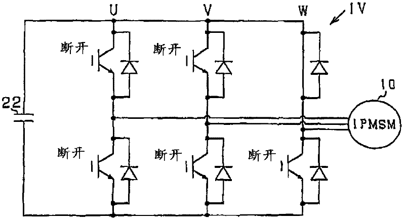
[0053] Figure 6A to Figure 6C is a diagram describing the principle of failsafe processing against a failure according to the second embodiment. Such as Figure 6A As shown, in the phase with the short-circuit fault (phase W), the non-faulty arm is switched on. Also in this case, if Figure 6B with Figure 6C As shown, the same advantages as those in the first embodiment can be obtained.

[0054] Figure 7 Failsafe processing against failures according to the present embodiment is shown. For example, this process is repeatedly executed by the control device 40 at a predetermined cycle. exist Figure 7 In, for convenienc...


PUM


Abstract

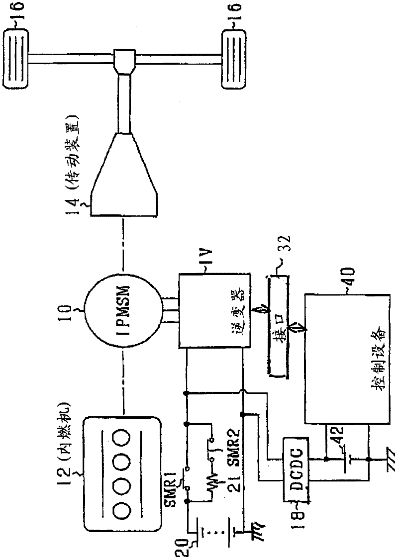
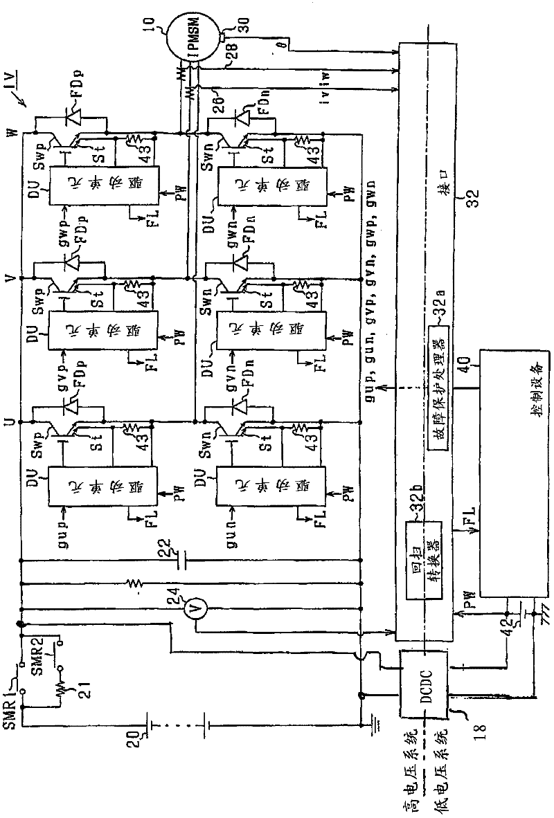
A control apparatus for a rotary electric machine has a DC-AC converting circuit with high- and low-potential-side switching elements to compose an inverter. In this apparatus, a connecting / disconnecting circuit is arranged to be electrically opened and closed between the DC-AC converting circuit and a power supply. A determining member determines whether or not the high-potential-side and low-potential-side switching elements have a malfunction. A failsafe performing element opens the connecting / disconnecting circuit and turns on both the high-potential-side and low-potential-side switching elements residing in a part of the inverter, when it is determined that there is caused a malfunction in the switching elements. The turned-on high-potential-side and low-potential-side switching elements realizes a short-circuit state therein.

Description

technical field [0001] The present invention relates to a control device for a rotating electric machine, and more particularly to a control device equipped with a direct current-alternating current DC-AC converter having a switching element to control power from a direct current DC power supply to a rotating electric machine. Background technique [0002] Control devices of this type are known. For example, patent document JP-A-2007-312588 discloses a control device capable of switching on arms on one side of all phases, including arms with short-circuited switching elements. Therefore, the peak value of the current can be suppressed in each of the phases of the motor. [0003] In the control apparatus disclosed in the above patent documents, failsafe processing is performed to suppress the peak value of the current in each of the phases of the motor. When performing failsafe processing, it is necessary to drive the switching elements of the arms on one side of all phases...

Claims


Application Information

Patent Timeline
Patent Type & Authority Applications(China)
IPC IPC(8): H02P6/00H02P29/02B60K6/48B60K6/54B60L3/00B60L50/16H02M7/48H02P21/22H02P27/06
CPCH02P29/023H02P3/22Y02T10/7241B60L3/003Y02T10/7077B60L7/003Y02T10/642Y02T10/6221B60L3/04B60L2240/526H02P29/0243Y02T10/64
Inventor 辻浩也
Owner DENSO CORP
Features
  • R&D
  • Intellectual Property
  • Life Sciences
  • Materials
  • Tech Scout
  • Unparalleled Data Quality
  • Higher Quality Content
  • 60% Fewer Hallucinations
Learn More