
Eureka
For R&D, Eureka makes reading and utilizing patents & technical documents easy.
Eureka AIR
Designed for self-driven R&D workflows. Generate viable solutions, solve complex R&D challenges, empower your innovation with AI.

Eureka Materials
Designed for material experts only. Revolutionize your material R&D, from search, analyze, to developing new materials.

TechResearch
Generate reliable direction feasibility study reports for your R&D in just a few steps.

TechSeek
Discover and master advanced knowledge NOW. Basics, ideas, possibilities, all at once.

TechMind
As an expert in R&D Theories, TechMind can generates customized viable solutions instantly.

TechRisk
Analyze your overall solution with one click, know your potential R&D risks in advance.

TechMonitor
Get weekly tech updates, stay abreast of the latest tech innovations and key insights.
Plate measuring element
A technology for measuring components and plates, applied in general parts of printing machinery, printing, printing machines, etc., can solve the problem of not being able to accurately determine the center point of point clusters.
- Summary
- Abstract
- Description
- Claims
- Application Information
AI Technical Summary
Problems solved by technology
Method used
Image

Examples
Embodiment Construction
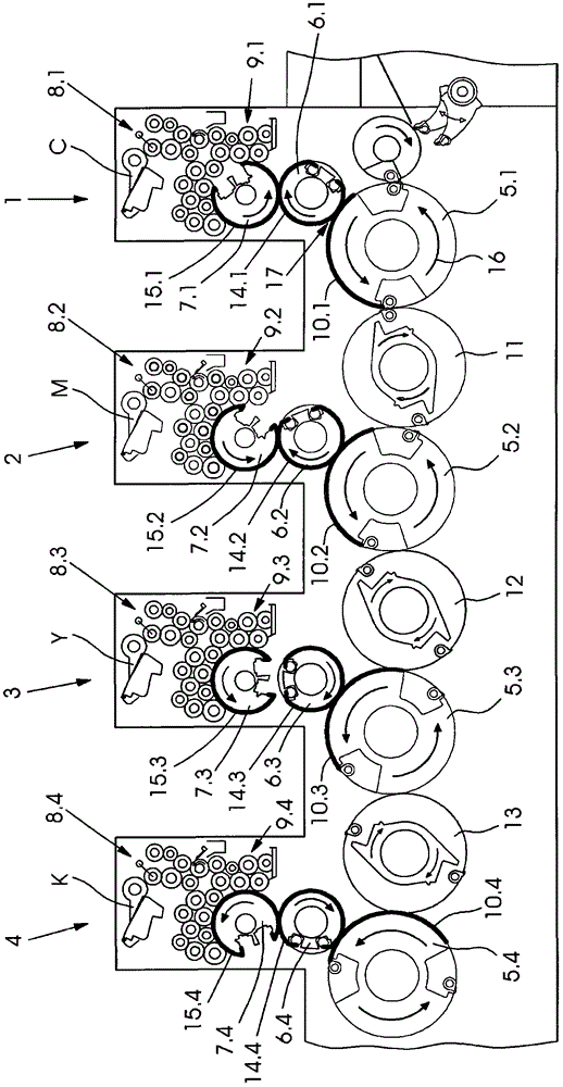
[0013] figure 1 Four printing units of an offset printing press are shown. Each printing unit 1 to 4 comprises an impression cylinder 5.1 to 5.4, a transfer cylinder 6.1 to 6.4 and a plate cylinder 7.1 to 7.4. An ink unit 8.1 to 8.4 and a dampening unit 9.1 to 9.4 are assigned to each plate cylinder 7.1 to 7.4. For conveying the sheets 10.1 to 10.4, transfer rollers 11 to 13 are located between the impression cylinders 5.1 to 5.4. The blankets 14.1 to 14.4 are stretched over the transfer cylinders 6.1 to 6.4. The printing plates 15.1 to 15.4 are stretched on the printing plate cylinders 7.1 to 7.4. During printing, the cylinder and roller rotate in the direction of arrow 16 .
[0014] During printing, the printing plates 15.1 to 15.4 are inked image-wise by means of corresponding ink units 8.1 to 8.4 and dampening units 9.1 to 9.4. The printing inks C, M, Y, K of the partial images reach the blankets 14.1 to 14.4 from the printing plates 15.1 to 15.4. If the sheets 10.1 ...
PUM
 Abstract
Description
Claims
Application Information
 - R&D Engineer
- R&D Manager
- IP Professional
- Industry Leading Data Capabilities
- Powerful AI technology
- Patent DNA Extraction
Browse by: Latest US Patents, China's latest patents, Technical Efficacy Thesaurus, Application Domain, Technology Topic, Popular Technical Reports.
© 2024 PatSnap. All rights reserved.Legal|Privacy policy|Modern Slavery Act Transparency Statement|Sitemap|About US| Contact US: help@patsnap.com