Locking system and switching device for a locking system

A technology of power distribution device and locking mechanism, which is applied in the field of power distribution device, can solve problems such as returning to the initial state, and achieve the effect of reliable locking

Active Publication Date: 2012-04-18
LIEBHERR AEROSPACE LINDENBERG
View PDF9 Cites 4 Cited by
  • Summary
  • Abstract
  • Description
  • Claims
  • Application Information

AI Technical Summary

Problems solved by technology

The disadvantage here is that the electromechanical operating device can no longer be returned to...

Method used


Image

  • Locking system and switching device for a locking system
  • Locking system and switching device for a locking system
  • Locking system and switching device for a locking system

Examples


Embodiment Construction

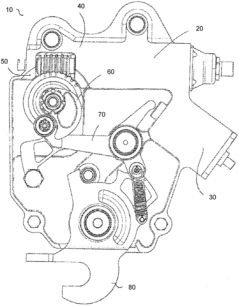
[0029] figure 1 A locking system 10 of an aircraft, here a locking system for landing gear of an aircraft, in particular an aircraft, is shown in a schematic front view. Such a locking system 10 can also be used in a corresponding variant for locking a door locking device of an aircraft. The locking system 10 is also referred to as an uplock.

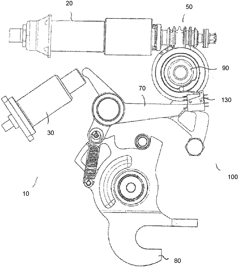
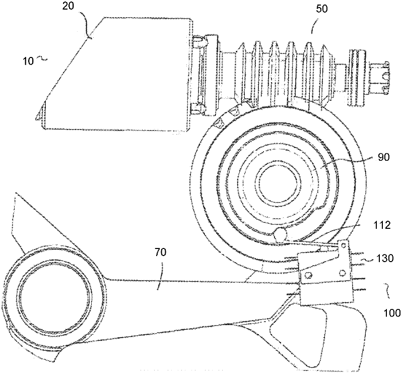
[0030] For reasons of redundancy, two drives 20 and 30 are provided, by means of which the locking system 10 can be actuated.

[0031] An electric drive 20 is therefore provided as the first drive, which can be a brush motor 20 for example. At the torque output, the electric motor 20 is associated, for example, with a planetary gear 40 and transmits the output torque to a shaft with a cam disk 60 , for example via a worm gear 50 . By means of usually for action according to figure 1 The view of the cam plate 60 being turned counterclockwise can move the actuating lever 70 such that the hook 80 moves from a first position, which is a...


PUM


Abstract

The present invention relates to a locking system, in particular a locking system for an aircraft, having at least one locking means which can be moved into at least one first position and into at least one second position, with the locking system having at least one switching apparatus by means of which the achieving of a defined end position of the locking means can be ensured and/or the locking system can be monitored.

Description

technical field [0001] The invention relates to a locking system, in particular for an aircraft, and to a power distribution device for a locking system. Background technique [0002] Contemporary aircraft today have retractable landing gear that is mostly hydraulic. In order to ensure the flight performance especially in high-speed flight, it is necessary that the landing gear system of the aircraft can be reliably retracted during flight, kept in place and can also be reliably extended as required, for example, during landing. [0003] Hitherto, secure holding in position has been achieved by locking systems which are mechanically coupled to the aircraft structure and form a form-fit connection with the undercarriage system in the retracted state of the undercarriage system. [0004] Only during an externally activated hook opening movement is the undercarriage system released in a form-fitting manner and deployed either hydraulically or by gravity. Because of relatively...

Claims


Application Information

Patent Timeline
IPC IPC(8): B64C25/26
CPCE05B81/05E05B81/38E05B81/54E05B81/14B64C25/26E05B81/42E05B81/58E05B81/10E05B81/74E05B81/06
Inventor K·沃尔夫M·埃芬格S·卡普斯
Owner LIEBHERR AEROSPACE LINDENBERG
Why Eureka
Try Eureka