Pumping machinery, pumping system and dispensing valves thereof, and method of operation of the pumping system

A technology of a pumping system and an operation method is applied to a pumping machine and an operation method of the pumping system. It can solve the problems of complex operation method, large switching resistance of distribution valve, complicated structure of distribution valve, etc., and achieve the effect of continuous pumping and simple structure.

Active Publication Date: 2014-10-15
SANY HEAVY IND CO LTD (CN)
View PDF5 Cites 0 Cited by
  • Summary
  • Abstract
  • Description
  • Claims
  • Application Information

AI Technical Summary

Problems solved by technology

[0005] Although the technical solution disclosed in the Chinese patent document CN1946937B can realize continuous pumping of materials, the technical solution requires two control slides and a corresponding operation method to realize connected pumping, which not only leads to a complicated structure of the distribution valve, Its disclosed operation method for realizing continuous pumping is also very complicated
[0006] In addition, in the technical solution disclosed in the Chinese patent document CN1946937B, in order to realize the state transition of the distribution valve, the control slides need to be arranged vertically; in this way, when the distribution valve performs state transitions, it is not only necessary to overcome the gravity and inertia of the control slides themselves, It is also necessary to overcome the pressure effect of the material in the material container on the control slide, resulting in a large switching resistance of the distribution valve

Method used


Image

  • Pumping machinery, pumping system and dispensing valves thereof, and method of operation of the pumping system
  • Pumping machinery, pumping system and dispensing valves thereof, and method of operation of the pumping system
  • Pumping machinery, pumping system and dispensing valves thereof, and method of operation of the pumping system

Examples


Embodiment Construction

[0052] The present invention will be described in detail below in conjunction with the accompanying drawings. The description in this part is only exemplary and explanatory, and should not be regarded as limiting the technical content disclosed in the present invention.

[0053] In this section, the mouth that enters the corresponding passage is the entrance of the passage, and the mouth that flows out of the corresponding passage is the exit of the passage.

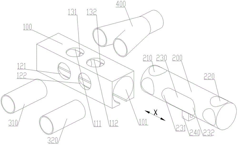
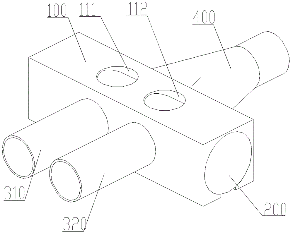
[0054] Please refer to figure 1 and Figure 2, figure 1 It is an exploded diagram of the dispensing valve of the pumping system provided by the present invention; diagram 2-1 It is an assembly diagram of the dispensing valve of the pumping system provided by the present invention, which also shows the structure of the dispensing valve in the first state; for the convenience of description, figure 1 And the Y-shaped joints of the two delivery cylinders and delivery pipes also shown in Figure 2.

[0055] The dispensing ...


PUM


Abstract

The invention discloses a pumping machine, a pumping system, a distributing valve thereof and an operation method of the pumping system. The distributing valve of the disclosed pumping system includes a valve body and a valve core, and the valve body and the valve core are in sliding fit; the valve body is provided with a feeding hole, two feeding and discharging holes and two pumping holes; the valve core forms two suction holes. channel and a pump material channel; in the extending direction of the inner slideway, the pump material channel has a predetermined size; when a suction channel is connected to a feed hole and an inlet and outlet hole, the other inlet and outlet hole passes through the pump material channel and A corresponding pump material hole communicates. When using the distribution valve, in any state of the distribution valve, at least one delivery cylinder communicates with the delivery pipe through the pump material channel; during the state transition process, at least one delivery cylinder remains in communication with the delivery pipe; At least one delivery cylinder can be communicated with the delivery pipe at any time; it provides the premise for the continuous and uninterrupted pumping of the pumping system.

Description

technical field [0001] The invention relates to a pumping technology, in particular to a distribution valve of a pumping system, a pumping system including the distribution valve, and a pumping machine including the pumping system. It also relates to a method of operating a pumping system. Background technique [0002] A commonly used pumping system usually includes a pumping power part, a material container, a distribution valve and a delivery pipe. The pumping power part includes a first delivery cylinder and a second delivery cylinder. The first delivery cylinder and the second delivery cylinder are arranged side by side at the front of the material container, and the pistons inside are respectively driven by a hydraulic cylinder for telescopic movement. There are many structures of distributing valves, commonly used ones are S-type valves, gate valves, C-shaped valves, skirt valves and so on. [0003] The working principle of the pumping system is: at the predetermined...

Claims


Application Information

Patent Timeline
Patent Type & Authority Patents(China)
IPC IPC(8): F04B53/10
Inventor 张裕生杨瞻勇黄奎荣
Owner SANY HEAVY IND CO LTD (CN)
Why Eureka
Try Eureka