
Clamp element

A clip element and clip technology are applied in the field of clip elements to achieve the effect of improving torsional rigidity

Active Publication Date: 2012-04-18
BROSE FAHRZEUGTEILE GMBH & CO KG HALLSTADT
View PDF7 Cites 4 Cited by
  • Summary
  • Abstract
  • Description
  • Claims
  • Application Information

AI Technical Summary

Problems solved by technology

However, this construction requires the installation of an additional locking tenon and also an additional work step using an assembly aid for assembly

Method used


Image

  • Clamp element
  • Clamp element
  • Clamp element

Examples


Embodiment Construction

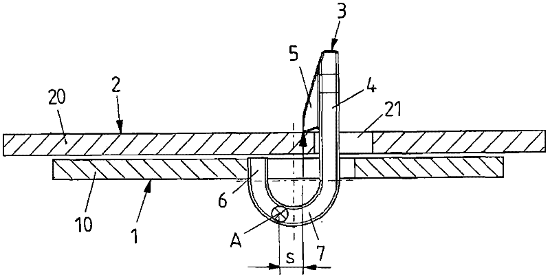
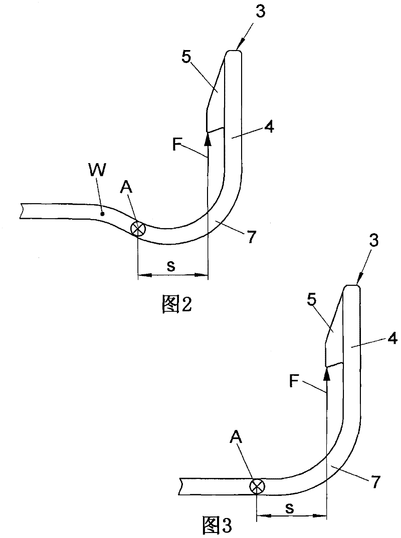
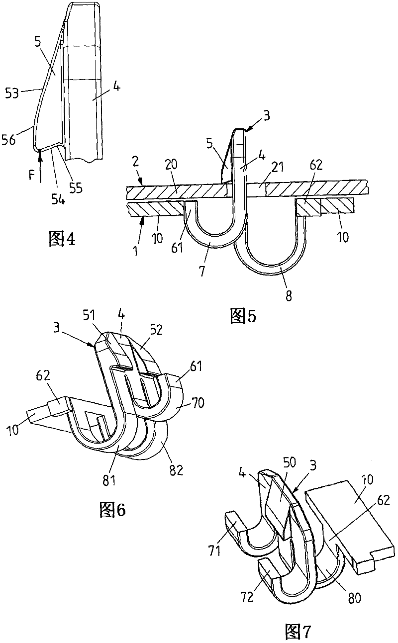
[0055] figure 1 A side view of the clip element 3 for the connection of the base body 10 of the component 1 , which is connected via the connection region 61 with the clip element 3 to the base plate 20 of the component 2 , is shown. The clip element 3 comprises a base 4 to which a clip hook 5 is integrally molded at one end and whose other end is connected to the base body 10 of the component 1 via a connection area 61 . Between the two ends, the base 4 has a spring leg 7 bent in a U-shaped manner, which encloses an angle of 180° between the area of ​​the base 4 where the clip hook 5 is integrally molded and the connection area 61 .

[0056] Figure 4 The clip hook 5 , shown enlarged in FIG. The surface of the base 4 extends vertically, or as Figure 4 As shown, an undercut 55 is formed extending from the base 4 at an acute angle.

[0057] In the base plate 20 of the assembly 2 , a clip socket 21 is provided in the form of an opening into which the clip element 3 is ins...


PUM


Abstract

The invention relates to a clamp element (3) which is provided with a base part (4). One end of the base part (4) is connected with a unit via a connecting area (61), and a clamp hook part (51) pointing to the connecting area (61) is integratedly molded to the other end of the base part (4). In order to build the clamping connection between the unit and an assembly, the clamp element (3) can be clamped into a clamp socket via a clamping-in force and can lock the clamp socket. According to the invention, the base part (4) is designed to form a virtual rotating axis, when a clamping-out force opposite to the clamping-in force acts a load on the clamping connection, a torque which rotates the virtual rotating axis and amplifies the clamping connection can be obtained along the direction of the clamp hook (51).

Description

technical field [0001] The invention relates to a clip element according to the preamble of claim 1 . Background technique [0002] In order to join sheet metal or plastic parts without using fastening devices such as screws, rivets, etc. and without deforming the parts to be joined, a clamping or snap-in connection is used, in which one part has at least one clip The hook or locking hook, while the other part contains at least one clip receptacle. To create a clamping or snap-in connection, the clip hooks, which are elastic perpendicular to their longitudinal direction, are clamped into the clip sockets, wherein when the components are joined perpendicular to the direction of introduction, the clip hooks yield elastically and in the end-of-installation position , which are latched with the edge of a clip socket with a latching edge. [0003] The degree of retention of the clip hooks to the latching receptacle, ie the clip-out force required to separate the parts, is large...

Claims


Application Information

Patent Timeline
Patent Type & Authority Applications(China)
IPC IPC(8): F16B5/12
CPCF16B2/22F16B5/0642
Inventor 托马斯・绍尔恩海默约拉姆・默谢尔
Owner BROSE FAHRZEUGTEILE GMBH & CO KG HALLSTADT
Learn More