Supercharge Your Innovation With Domain-Expert AI Agents!

Hydraulic flow collecting valve

A confluence valve and hydraulic technology, applied in the field of hydraulic confluence valve, can solve the problems of short service life, complex structure of confluence valve, low safety performance, etc., and achieve the effect of safe and reliable use, good effect and simple design structure.

Inactive Publication Date: 2012-04-18
浙江台意德塑机制造有限公司
View PDF2 Cites 4 Cited by
  • Summary
  • Abstract
  • Description
  • Claims
  • Application Information

AI Technical Summary

Problems solved by technology

However, the structure of the confluence valve is relatively complicated, the safety performance is not very high, and the service life is not long, so its structure still needs to be further improved.

Method used


Image

  • Hydraulic flow collecting valve
  • Hydraulic flow collecting valve
  • Hydraulic flow collecting valve

Examples


Embodiment Construction

[0024] The present invention will be further described in detail below in conjunction with the accompanying drawings and embodiments.

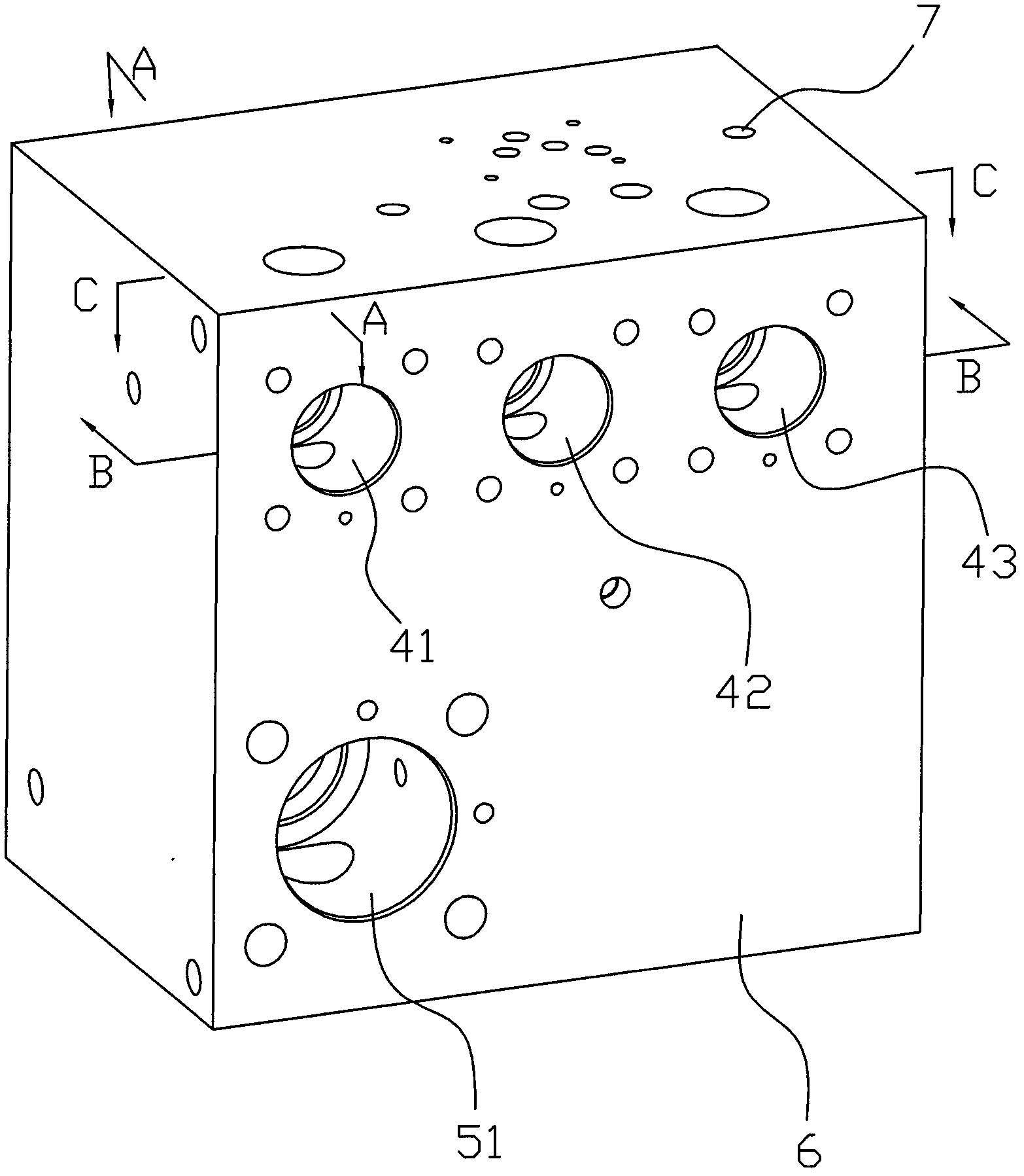
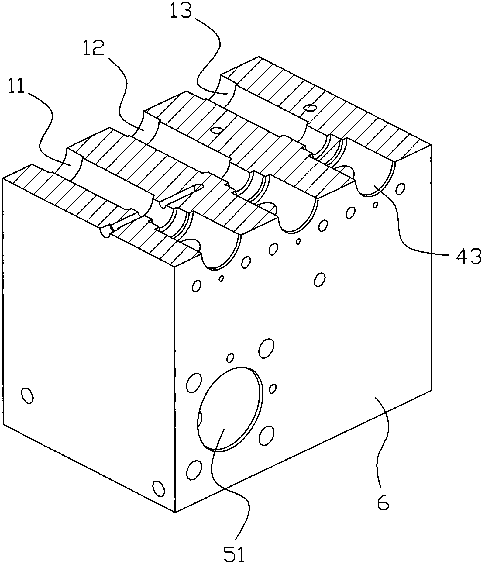
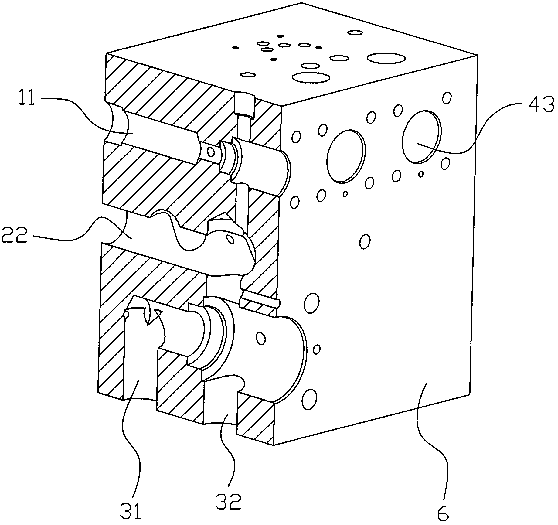
[0025] Such as Figures 1 to 10 As shown, the hydraulic confluence valve includes a valve body 6, the valve body 6 is a hexahedron, and several through cavities are respectively arranged inside it, wherein one end of the first hydraulic chamber 11 is connected with the first oil pump through a pipeline, and the other end is connected with the first oil pump through a pipeline. The first one-way valve chamber 41 communicates with the first confluence chamber 21 , one end of the second hydraulic chamber 12 is connected to the second oil pump through a pipeline, and the other end is communicated with the first confluence chamber 21 through the second one-way valve chamber 42 , one end of the third hydraulic chamber 13 is connected to the third oil pump through a pipeline, and the other end is connected to the first confluence chamber 21 through t...


PUM


Abstract

The invention discloses a hydraulic flow collecting valve, which comprises a valve body (6). The hydraulic flow collecting valve is characterized in that: a plurality of through cavities are formed in the valve body (6), wherein one end of a first hydraulic cavity (11) is connected with a first oil pump, and the other end of the first hydraulic cavity (11) is communicated with a flow collecting cavity through a first one-way valve cavity (41); one end of a second hydraulic cavity (12) is connected with a second oil pump, and the other end of the second hydraulic cavity (12) is communicated with a flow collecting cavity through a second one-way valve cavity (42); one end of a third hydraulic cavity (13) is connected with a third oil pump, and the other end of the third hydraulic cavity (13) is communicated with a flow collecting cavity through a third one-way valve cavity (43); and the flow collecting cavities are communicated with working valve cavities, and are communicated with backflow cavities through safety valve cavities. The hydraulic flow collecting valve has the advantages that: the hydraulic flow collecting cavity comprises three paths of oil supply hydraulic cavities, four paths of backflow cavities and three paths of flow collecting cavities which are required, has a simple structure, can supply working valve hydraulic oil for different parts, and is convenient and practical; in addition, the safety valve cavities are formed in the valve, safety valves can be automatically opened when pressure exceeds a certain value, and the oil can flow away from the backflow cavities, so the hydraulic flow collecting valve is safe, reliable and good in effect.

Description

technical field [0001] The invention relates to the technical field of valve body manufacture, in particular to a hydraulic confluence valve. Background technique [0002] The existing patent number is 200820187783.9. The Chinese utility model patent titled "Three-way Hydraulic Convergence Valve" discloses a three-way hydraulic confluence valve, including a valve body, which is characterized in that the valve body is a hexahedron with three holes on its top surface. There are three valve seats respectively in the valve seat, a cone valve, compression spring and spring seat are arranged in the valve seat, the valve seat is fixed on the valve body by the oil outlet block and bolts, and the corresponding two sides of the oil outlet block are respectively connected to the pressure gauge. The hole and the oil outlet communicate with the three cone valves; there are three pairs of six connecting holes on the right, front and left sides of the middle and lower part of the valve bod...

Claims


Application Information

Patent Timeline
Patent Type & Authority Applications(China)
IPC IPC(8): F16K11/22F16K27/00
Inventor 孙吉
Owner 浙江台意德塑机制造有限公司
Features
  • R&D
  • Intellectual Property
  • Life Sciences
  • Materials
  • Tech Scout
  • Unparalleled Data Quality
  • Higher Quality Content
  • 60% Fewer Hallucinations
Learn More