Supercharge Your Innovation With Domain-Expert AI Agents!

Coordinate normalizing method of electromagnetic induction device and electromagnetic induction device

A technology of electromagnetic induction and coordinate correction, applied in the direction of electrical digital data processing, input/output process of data processing, instruments, etc., can solve problems such as inconsistent motion trajectories, and achieve the effect of improving experience

Active Publication Date: 2014-08-27
BEIJING HANWANG PENGTAI TECH CO LTD
View PDF2 Cites 0 Cited by
  • Summary
  • Abstract
  • Description
  • Claims
  • Application Information

AI Technical Summary

Problems solved by technology

This method uses the measured coordinate values ​​and time coefficients of different contact points of the electromagnetic pen on the electromagnetic board to obtain the actual coordinates of the electromagnetic pen when it moves on the electromagnetic board, so as to solve the problem that the coordinate values ​​actually measured by the electromagnetic board are inconsistent with the motion trajectory of the electromagnetic pen. question

Method used


Image

  • Coordinate normalizing method of electromagnetic induction device and electromagnetic induction device
  • Coordinate normalizing method of electromagnetic induction device and electromagnetic induction device
  • Coordinate normalizing method of electromagnetic induction device and electromagnetic induction device

Examples


Embodiment 1

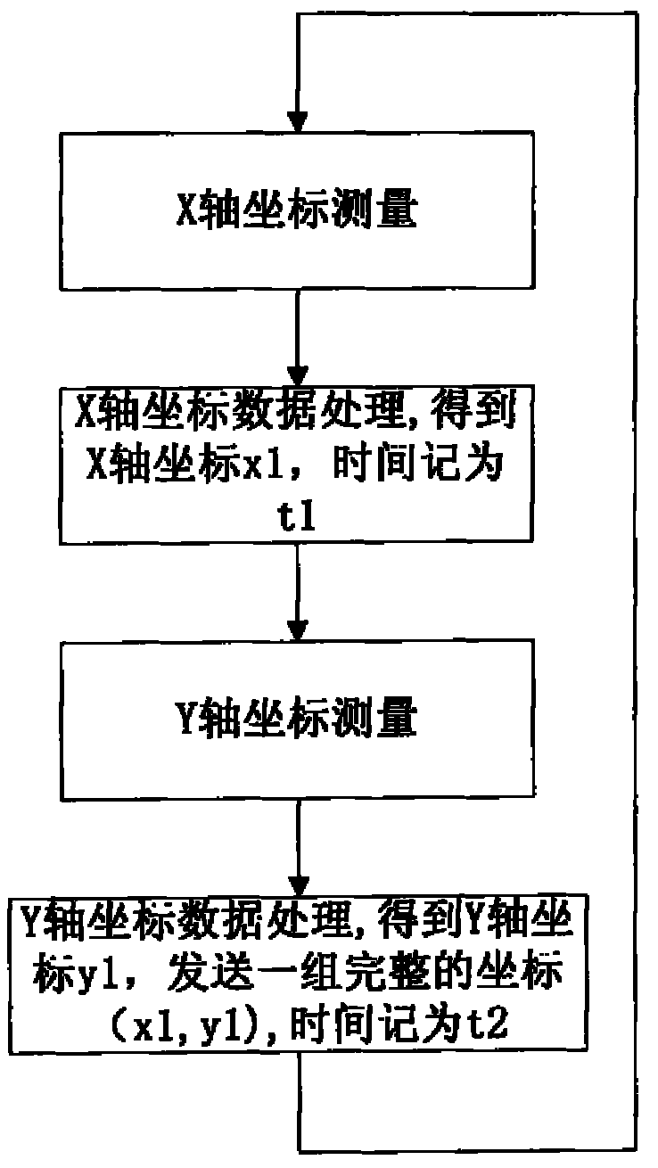
[0048] When the electromagnetic pen moves on the electromagnetic board, first measure the X-axis coordinates, and then measure the Y-axis coordinates as an example to illustrate the coordinate correction method.

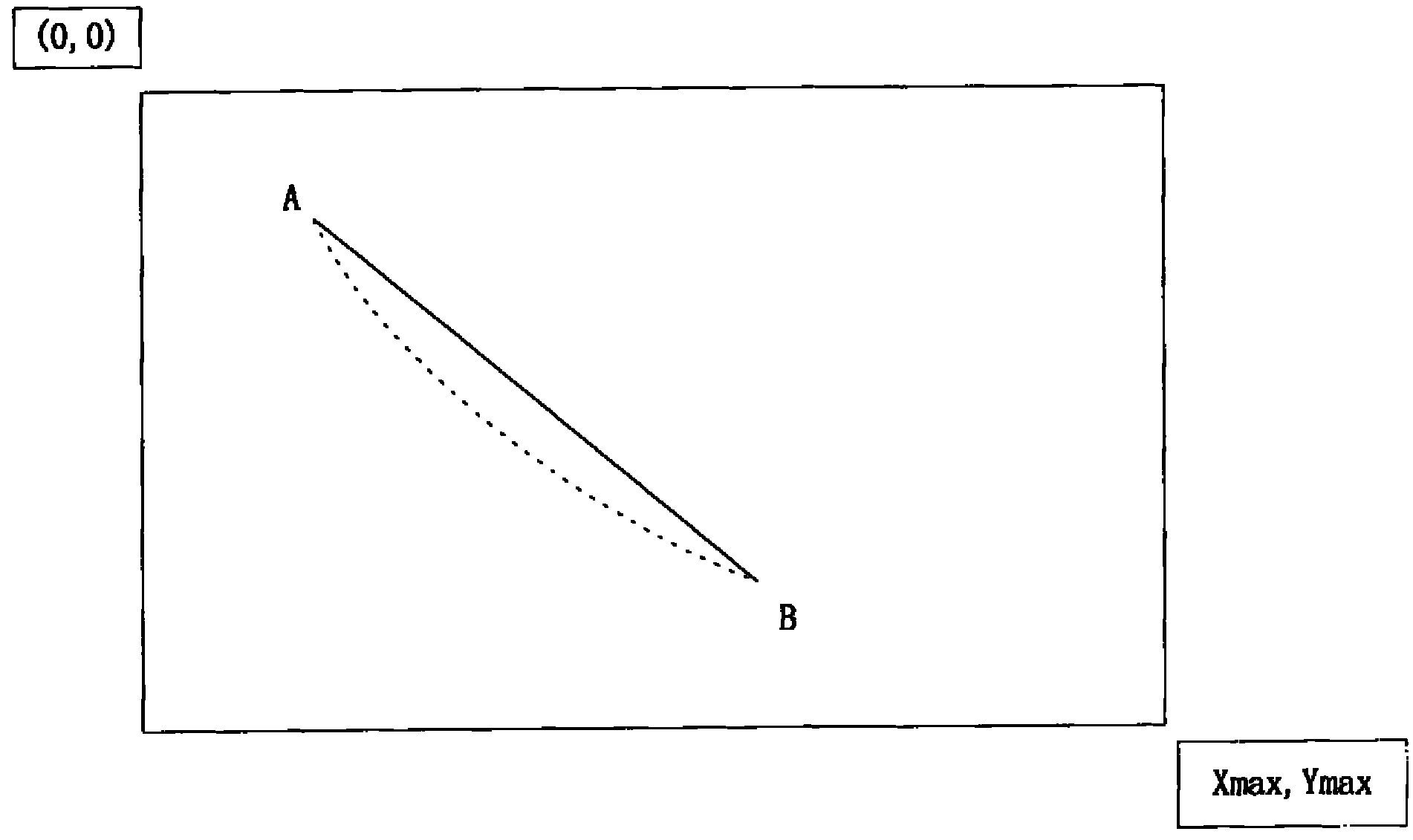
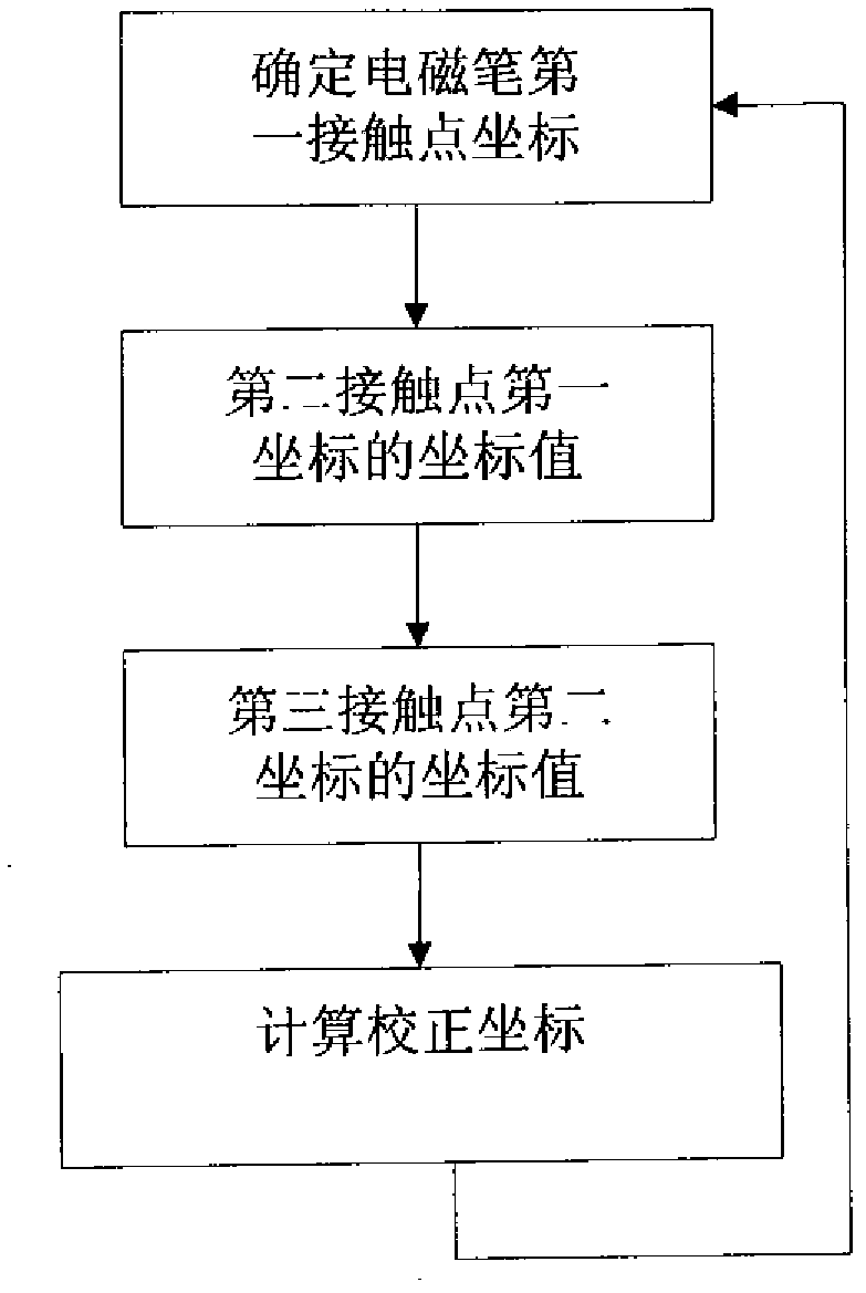
[0049] Figure 4 It is a schematic diagram of the moving track of the electromagnetic pen. Point C in the figure is a contact point when the electromagnetic pen moves on the electromagnetic board, and its coordinates are (x1, y1). After the electromagnetic board measures and corrects the coordinates of point C, the controller in the electromagnetic board performs data processing and sends coordinates (x1, y1) to the host. This period of time is recorded as t1. After time t1, the electromagnetic pen moves to point D. At this time, the electromagnetic board control circuit is set to measure the X-axis coordinate of point D first, and the X-axis coordinate value is recorded as x2. Then the controller in the electromagnetic board needs to process the X-axis measurement ...

Embodiment 2

[0053] Next, the coordinate correction method of the present invention will be described by taking the electromagnetic pen firstly measuring the Y-axis coordinates and then measuring the X-axis coordinates as an example when the electromagnetic pen moves on the electromagnetic board.

[0054] Figure 5 It is a schematic diagram of the moving track of the electromagnetic pen. Point C1 in the figure is a contact point when the electromagnetic pen moves on the electromagnetic board, and its coordinates are (x1, y1). After the electromagnetic board measures and corrects the coordinates of point C1, the controller in the electromagnetic board performs data processing and sends the coordinates (x1, y1) to the host. This period of time is recorded as t1. After the time t1 passes, the electromagnetic pen moves to point D1. At this time, the electromagnetic board control circuit is set to measure the Y-axis coordinate of point D1 first, and the Y-axis coordinate value is recorded a...


PUM


Abstract

The invention relates to a coordinate normalizing method of an electromagnetic induction device and an electromagnetic induction device, wherein the method comprises the following steps: determining the coordinate of a first contact point (contacted by an electromagnetic pen) on an electromagnetic board; when the electromagnetic pen, after a first time t1, moves from the first contact point to a second contact point on the electromagnetic board, determining a first coordinate value of the second contact point; when the electromagnetic pen, after a second time t2, moves from the second contact point to a third contact point on the electromagnetic board, determining a second coordinate value of the third contact point; and according to the coordinate value of the first contact point, the first coordinate value of the second contact point and the second coordinate value of the third contact point as well as the first time t1 and the second time t2, obtaining the actual coordinate value of a second coordinate of the second contact point. By using the coordinate normalizing method disclosed by the invention, the problem that the actual motion trail of the electromagnetic pen is not coincident with a measured coordinate can be solved, so that a coordinate value measured by the electromagnetic board is extremely close to the actual motion coordinate value of the electromagnetic pen.

Description

technical field [0001] The invention relates to coordinate detection of an electromagnetic induction device, in particular to an electromagnetic induction device and a coordinate correction method of the device. Background technique [0002] With the continuous development of information technology, electromagnetic induction devices have been applied in many fields. The electromagnetic induction device is the same as the keyboard, mouse and tablet, and it is an input device. The electromagnetic induction device is composed of an electromagnetic board and an electromagnetic pen. It is mainly used in computer painting, which is convenient for creators to find the feeling of real painting when creating. The current electromagnetic induction device usually transmits data such as the track coordinates of the electromagnetic pen moving on the electromagnetic board, the pressure and the inclination angle of the electromagnetic pen to the computer, so as to realize the purpose of h...

Claims


Application Information

Patent Timeline
Patent Type & Authority Patents(China)
IPC IPC(8): G06F3/046G06F3/0354
Inventor 王红岗伍松林
Owner BEIJING HANWANG PENGTAI TECH CO LTD
Features
  • R&D
  • Intellectual Property
  • Life Sciences
  • Materials
  • Tech Scout
  • Unparalleled Data Quality
  • Higher Quality Content
  • 60% Fewer Hallucinations
Learn More