Synchronous switch control circuit for common electromagnetic contactor

An electromagnetic contactor, synchronous switch technology, applied in circuits, relays, electrical components, etc., can solve problems such as impact and high current

Active Publication Date: 2012-04-18
北京馨容纵横科技发展有限公司
View PDF9 Cites 18 Cited by
  • Summary
  • Abstract
  • Description
  • Claims
  • Application Information

AI Technical Summary

Problems solved by technology

Therefore, it is traditionally recognized that switching with an ordin

Method used


Image

  • Synchronous switch control circuit for common electromagnetic contactor
  • Synchronous switch control circuit for common electromagnetic contactor
  • Synchronous switch control circuit for common electromagnetic contactor

Examples


Embodiment Construction

[0021] The present invention will be described in detail below in conjunction with the accompanying drawings.

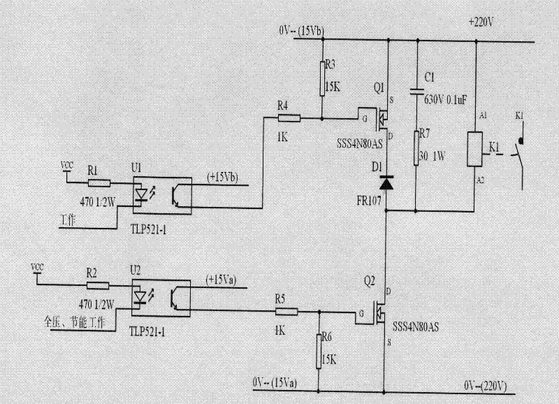
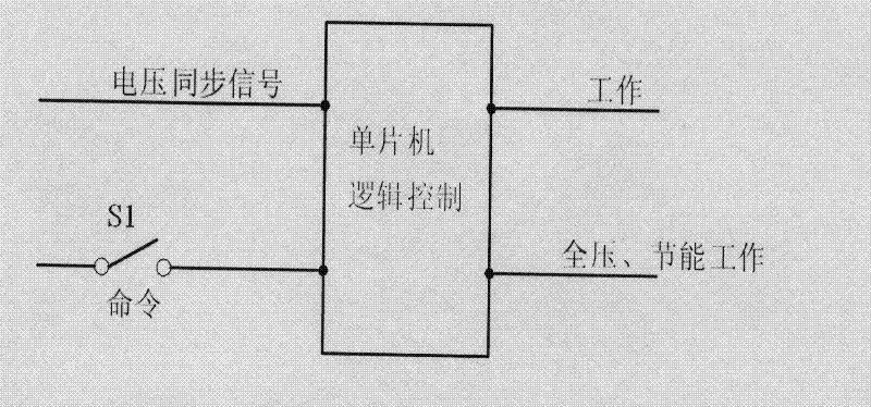
[0022] figure 1 A synchronous switch control circuit for a common electromagnetic contactor is shown; figure 2 The schematic diagram of the microcontroller logic control circuit is shown. Such as figure 1 As shown, the contactor adopts the GSC1-40 type, and the two ends A1 and A2 of the contactor K1 coil are connected in parallel to the series absorbing circuit formed by the capacitor C1 and the resistor R7, and are also connected in parallel to another circuit composed of the diode D1 and the MOSFET switch tube Q1. A series snubber circuit. Among them, capacitor C1 adopts 630V 0.1uF capacitor; resistor R7 adopts 30 ohm 1W resistor; diode D1 adopts FR107; MOSFET switch tube Q1 adopts SSS4N80AS. The MOSFET switch tube Q2 is connected in series with the coil of the contactor K1 to the 220V DC power supply, and the MOSFET switch tube Q2 also adopts SSS4N80AS. Q2 i...


PUM


Abstract

The invention discloses a synchronous switch control circuit for a common electromagnetic contactor and belongs to the technical field of reactive compensation and harmonic filtering of a power system. The common electromagnetic contactor is adopted by a synchronous switch, a control circuit for a contactor coil is properly designed on the premise that the structure of the common contactor is not changed, power supply of an alternating current (AC) 220V coil of an AC contactor is changed into power supply of a direct current (DC) 220V stabilized voltage supply, the switch on of the switch is designed into total voltage coil suction and is in low-voltage electricity-saving suction, and the switch off of the switch is designed into oscillating discharge of a coil inductor L, a capacitor C and a resistor R, inductance energy of the coil is rapidly absorbed, and a function of rapidly disconnecting the contactor is realized. The requirement of the synchronous switch is met through the common electromagnetic contactor, an expected effect is achieved, and due to the adoption of the common electromagnetic contactor, an accurate shock-free current switched capacitor bank and a reactor are implemented.

Description

technical field [0001] The invention relates to the technical field of reactive power compensation and harmonic filtering of electric power systems, in particular to a synchronous switch control circuit. Background technique [0002] After investigation, the patent No. 200920105307.2 is "a 2-control 3 pre-charging phase-controlled switch circuit for switching capacitor banks", and the patent No. 200910076776.0 is "a 2-control 3 pre-charging phase-controlled switch circuit for switching capacitor banks. Circuit" and the patent No. 01113435.6 patent "an electronic zero-switching contactor" and the like are mentioned in documents such as using existing mechanical contact switches to switch capacitors. However, it is generally believed that when the mechanical contact switch is used for switching, the three-phase switch switches the capacitor at a random and uncertain grid voltage point, and the current impact is large, with 4 times to 10 times or even 20 times the rated current...

Claims


Application Information

Patent Timeline
IPC IPC(8): H01H47/00
Inventor 杨建宁
Owner 北京馨容纵横科技发展有限公司
Why Eureka
Try Eureka