
Fluid supply system and method of operating a fluid supply system

A technology of fluid supply and mass flow, which is applied in transportation and packaging, components with teeth, thin material processing, etc. It can solve the problems of fluid system loss and other problems, and achieve the effect of reducing flow loss and reducing pressure drop

Inactive Publication Date: 2012-04-18
GM GLOBAL TECH OPERATIONS LLC
View PDF1 Cites 3 Cited by
  • Summary
  • Abstract
  • Description
  • Claims
  • Application Information

AI Technical Summary

Problems solved by technology

However, the fluid system still involves high flow generation losses, requiring a relatively high amount of energy to provide a specific cooling mass flow

Method used


Image

  • Fluid supply system and method of operating a fluid supply system
  • Fluid supply system and method of operating a fluid supply system
  • Fluid supply system and method of operating a fluid supply system

Examples


Embodiment Construction

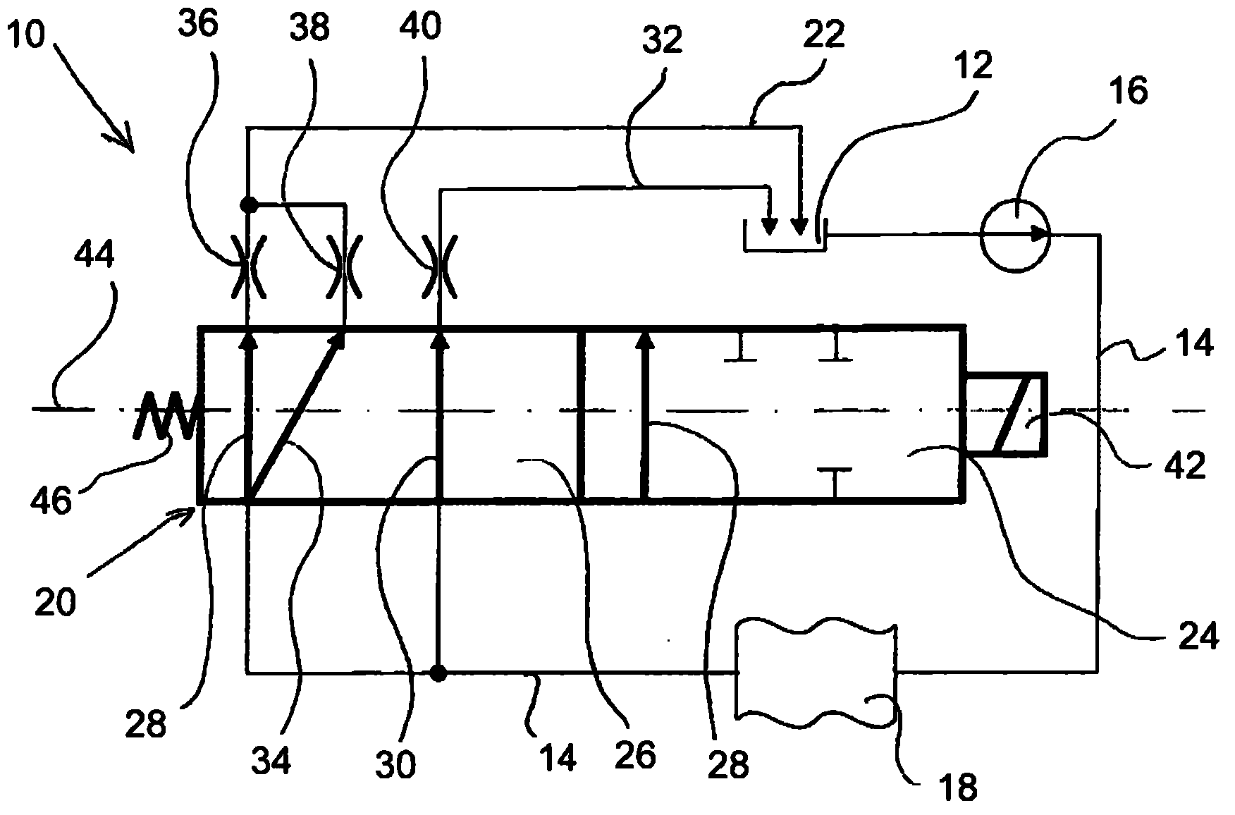
[0023] figure 1 The fluid supply system 10 shown in includes an oil sump 12 through which a transmission oil mass flow Feed to the cooling channel 14. The cooling channel 14 includes a radiator 18 which cools the transmission oil, in particular after it has cooled the automatic transmission, not shown. The cooling channel 15 is connected via a displacement valve 20 to the mass flow Lubricating oil channel 22, said lubricating oil channel terminates at oil groove 12.

[0024] The shift valve includes a figure 1 The first chamber 24 on the right side of the middle displacement valve 20, and is arranged in figure 1 The second chamber on the left side of the shift valve 20. Via the first chamber 24 a first valve state can be set, with which the cooling channel 14 is connected to the lubricating oil channel 22 via a first valve path 28 without any branching. In the first valve state, the cooling mass flow corresponds to the lubrication mass flow

[0025] When the shift...


PUM


Abstract

A fluid supply system (10) for cooling and lubricating a transmission of an automobile, comprising a cooling channel (14) and a lubrication channel (22).The lubrication channel (22) communicates with the cooling channel (14) via a shift valve (20), wherein the shift valve (20) is adapted to provide at least a first valve status, by which the cooling channel (14) is connected to the lubrication channel (22) via only one first valve path (28), and a second valve status, by which the cooling channel (14) is connected to the lubrication channel (22) via at least the first valve path (28) and by which the cooling channel (14) is connected in addition via a second valve path (30) to a bypass channel (32) bypassing the lubrication channel (22).

Description

technical field [0001] The invention relates to a fluid supply system for cooling and lubricating a motor vehicle transmission, in particular an automatic transmission, and a method for operating the fluid supply system. Background technique [0002] From document US 2007 / 0000728 A1, a fluid supply system for cooling and lubricating an automatic transmission is known, in which the cooling channel for cooling the automatic transmission is branched into a lubrication channel for lubricating the automatic transmission and bypasses the lubrication towards the oil sump channel bypass channel. With such a fluid supply system, the spin loss of the transmission can be reduced. However, the fluid system still involves high flow generation losses, requiring a relatively high amount of energy to provide a given cooling mass flow. There will always be a need to further reduce flow generation losses in fluid supply systems. Contents of the invention [0003] It is an object of the p...

Claims


Application Information

Patent Timeline
Patent Type & Authority Applications(China)
IPC IPC(8): F16H57/04
CPCF16H57/0413F16H57/0446F16H2061/0037Y10T74/19991Y10T137/0318Y10T137/8593Y10T137/87338F16H57/0415F16H57/042
Inventor F.皮格纳特
Owner GM GLOBAL TECH OPERATIONS LLC
Learn More