A New Type of Durable Magnetized Anchor Rod
What is Al technical title?
Al technical title is built by PatSnap Al team. It summarizes the technical point description of the patent document.
A bolt and durable technology, applied in the installation of bolts, mining equipment, earthwork drilling and mining, etc., can solve the problems of bolt support strength reduction, back buckle pre-tightening force, bolt failure, etc., to avoid bolt fatigue Effects of damage and corrosion, relaxation of load transfer, and enhancement of bolt strength
Active Publication Date: 2019-04-30
ANHUI UNIV OF SCI & TECH
View PDF8 Cites 1 Cited by
Summary
Abstract
Description
Claims
Application Information
AI Technical Summary
This helps you quickly interpret patents by identifying the three key elements:
Problems solved by technology
Method used
Benefits of technology
Problems solved by technology
During the support process of the pipe-seam anchor, the anchoring force is very sensitive to the change of the hole diameter difference, and the anchoring force of the anchor is greatly affected by the drilling factors, and the anchoring performance is unstable; the hydraulic expansion anchor is directly in contact with the outside world during the support. , easy to be corroded by moisture, causing the bolt to fail; due to the large pitch of the threaded steel bolt and the difficulty in controlling the cooperation between the thread and the nut, it is difficult to apply a large pre-tightening force, and the pre-tightening force is often reduced due to back-off in field use ; As a result, the bolt cannot control the surrounding rock in a three-dimensional stress state for a long time, resulting in a reduction in the strength of the bolt support
Method used
Image
Click on the blue label to locate the original text in one second.
Reading with bidirectional positioning of images and text.
Examples
Embodiment Construction
[0035] The present invention will be further described below in conjunction with accompanying drawing:
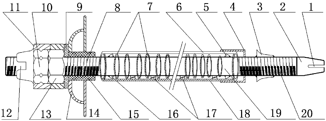
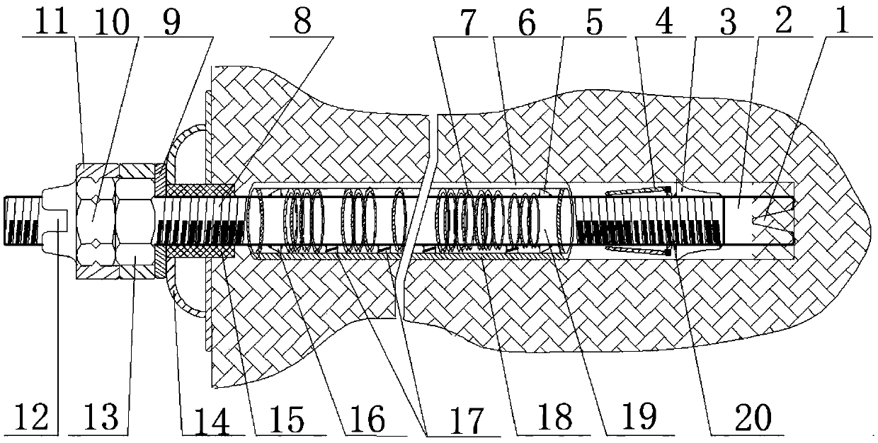
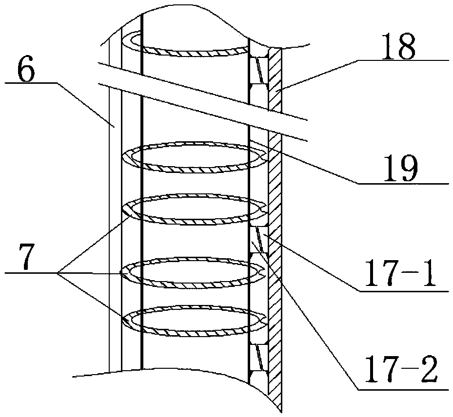
[0036] Working principle: The tapered end sleeve 2 with a symmetrical gap is used as a guiding element to drill the anchor rod body into the borehole. When the wide end of the tapered stop nut 3 is embedded in the surrounding rock deep in the borehole, the The threaded section 20 at the front end of the rod body constitutes a helical pair, which converts the rotary motion of the anchor rod body 19 into the axial propulsion movement of the borehole, thereby driving the claw-shaped elastic anti-expansion outer bushing 4 together with the threaded section 20 at the front end of the anchor rod body to the deep part of the borehole Pushing forward, the symmetrically distributed elastic claws 4-1 disengage and release the elastic magnetized slotted steel pipe 18. At the same time, the elastic claws 4-1 shrink radially and tightly fit the threaded section 20 at the front end of the...
PUM
Abstract
The invention discloses a novel durable magnetization anchor rod which comprises an anchor rod body, a conical end sleeve, a conical block nut, a claw-shaped elastic anti-expansion outer bushing, a concave spring ring, an elastic magnetization slotting steel pipe, a rubber bushing, an arch tray, an antifriction gasket, an opposite-abutting thickening nut fastening mechanism. The novel durable magnetization anchor rod is characterized in that the conical end sleeve guides the anchor rod body to be drilled into a drill hole, the conical block nut and the deep hole wall of the drill hole form a self-locking structure, the anchor rod body can be pushed axially, the claw-shaped elastic anti-expansion outer bushing is moved to the end of the anchor rod body, the elastic magnetization slotting steel pipe is released, claw teeth are retracted, the concave spring is compressed axially, the elastic magnetization slotting steel pipe is expanded, a wedge block is fitted, the outer wall of the steel pipe and the wall of the drill hole are extruded tightly, and the opposite-abutting thickening nut fastening mechanism compresses the arch tray to exert pretightening force on the anchor rod. On one hand, the anchor rod can stabilize a rock layer by enabling surrounding rock to be in the three-way stress state; on the other hand, the effective action time of the pretightening force of the anchor rod on the surrounding rock can be prolonged, the durability of the anchor rod can be improved, and the supporting efficiency can be improved.
Description
technical field [0001] The invention relates to the technical field of coal mine underground or tunnel support, in particular to a novel durable magnetized anchor rod, which is used to stabilize rock formations and prevent them from breaking or collapsing. Background technique [0002] At present, the bolt support technology has been widely used in the tunnel support of various projects such as mine roadways and railways, hydropower, and slopes at home and abroad. . With the maturity of rock bolt stabilization technology, the application in mine roadway or tunnel support is becoming more and more important. There are many types of traditional anchors. Through the use of different types of anchors in engineering, it is found that the existing anchors have poor durability during the support process, it is difficult to apply a large pre-tightening force, the anchoring performance is unstable, and the support strength Low main disadvantage. For example, the invention patent (...
Claims
Application Information
Patent Timeline
Application Date:The date an application was filed.
Publication Date:The date a patent or application was officially published.
First Publication Date:The earliest publication date of a patent with the same application number.
Issue Date:Publication date of the patent grant document.
PCT Entry Date:The Entry date of PCT National Phase.
Estimated Expiry Date:The statutory expiry date of a patent right according to the Patent Law, and it is the longest term of protection that the patent right can achieve without the termination of the patent right due to other reasons(Term extension factor has been taken into account ).
Invalid Date:Actual expiry date is based on effective date or publication date of legal transaction data of invalid patent.