
Self-locking descending bracket

A technology of self-locking and oblique blocks, which can be used in washing equipment, textiles and papermaking, household appliances, etc., and can solve problems such as inconvenience and easy drop of the bracket.

Inactive Publication Date: 2010-07-07
程宇鸣
View PDF0 Cites 2 Cited by
  • Summary
  • Abstract
  • Description
  • Claims
  • Application Information

AI Technical Summary

Problems solved by technology

[0003] In order to solve the problem that the traditional rack for drying clothes is easy to fall and inconvenient to use, the patent of this invention provides a rack with self-locking and lowering function that can set the use level according to the user's needs, and is very convenient to use

Method used


Image

  • Self-locking descending bracket
  • Self-locking descending bracket
  • Self-locking descending bracket

Examples


Embodiment Construction

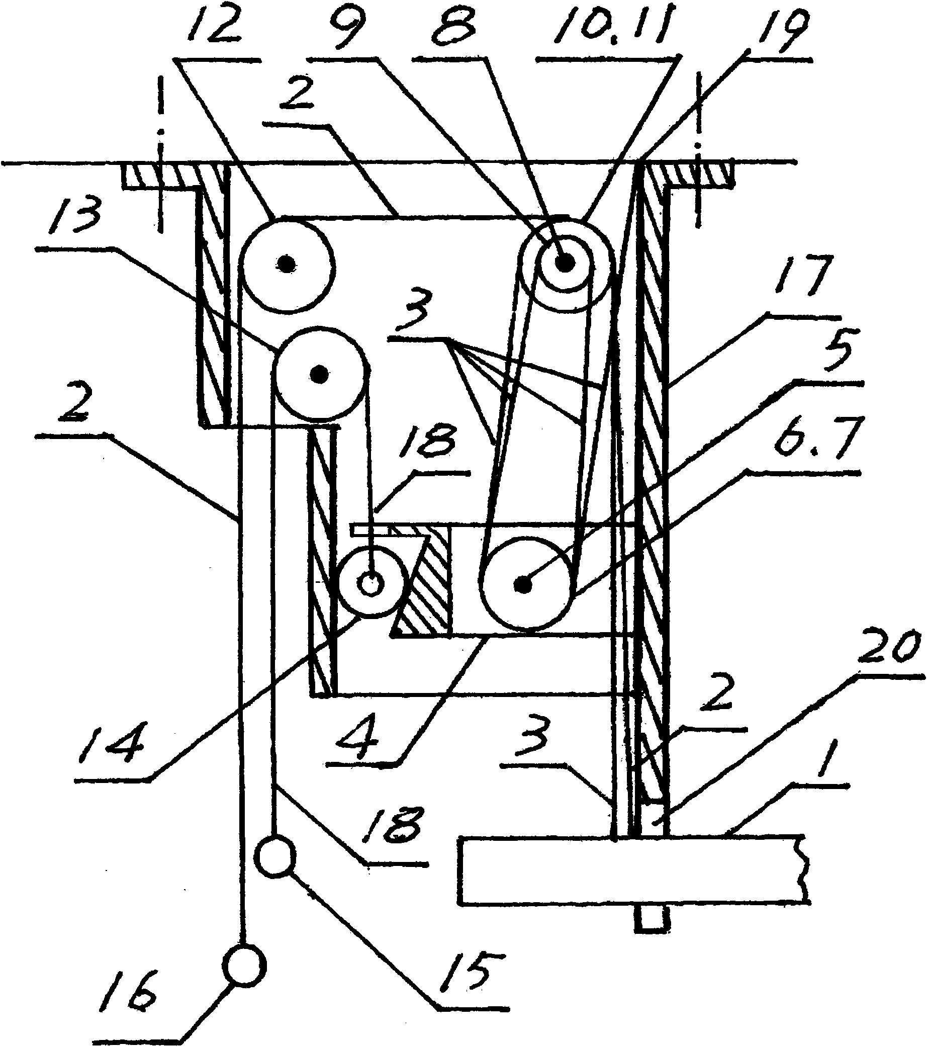
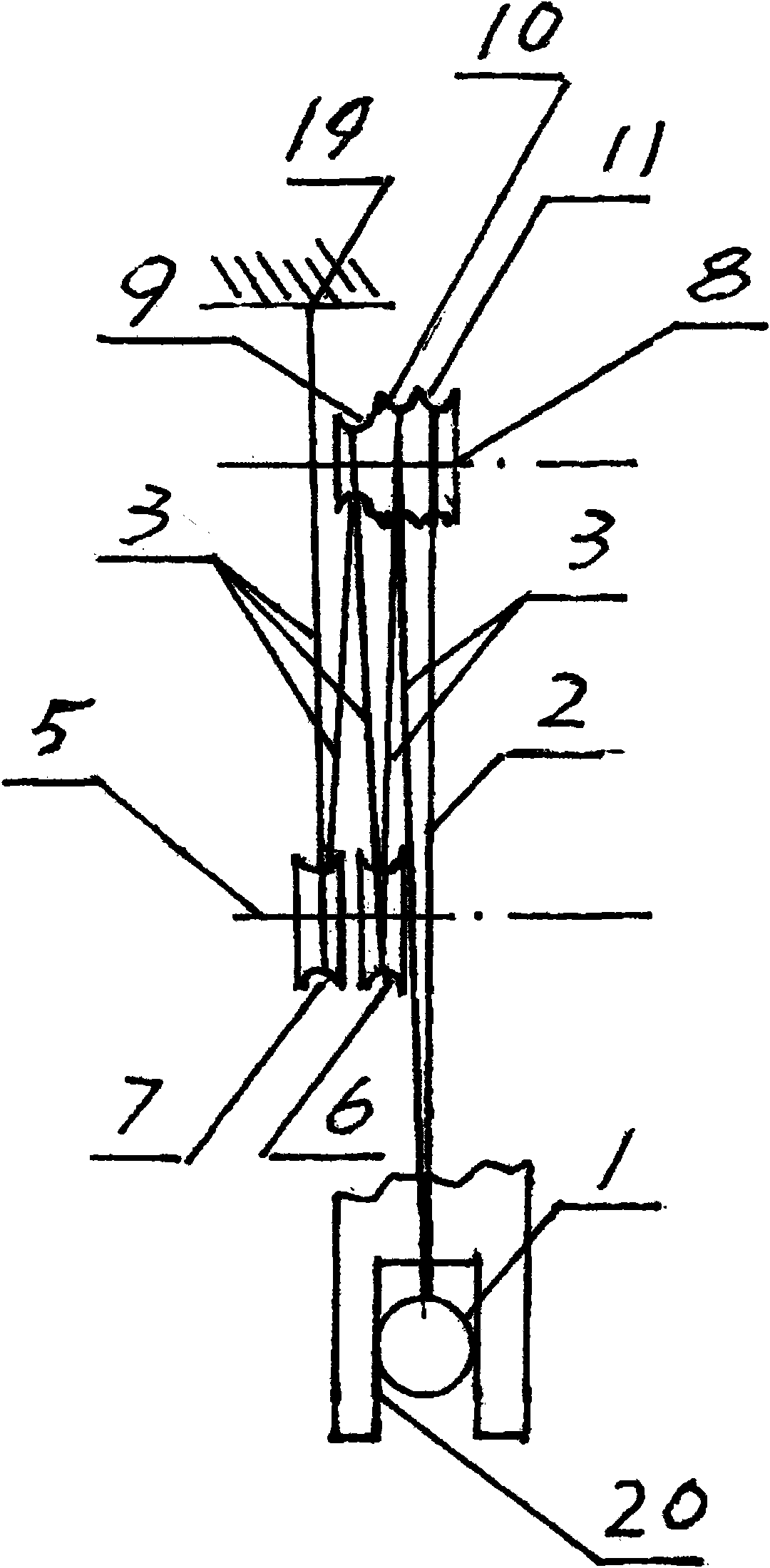
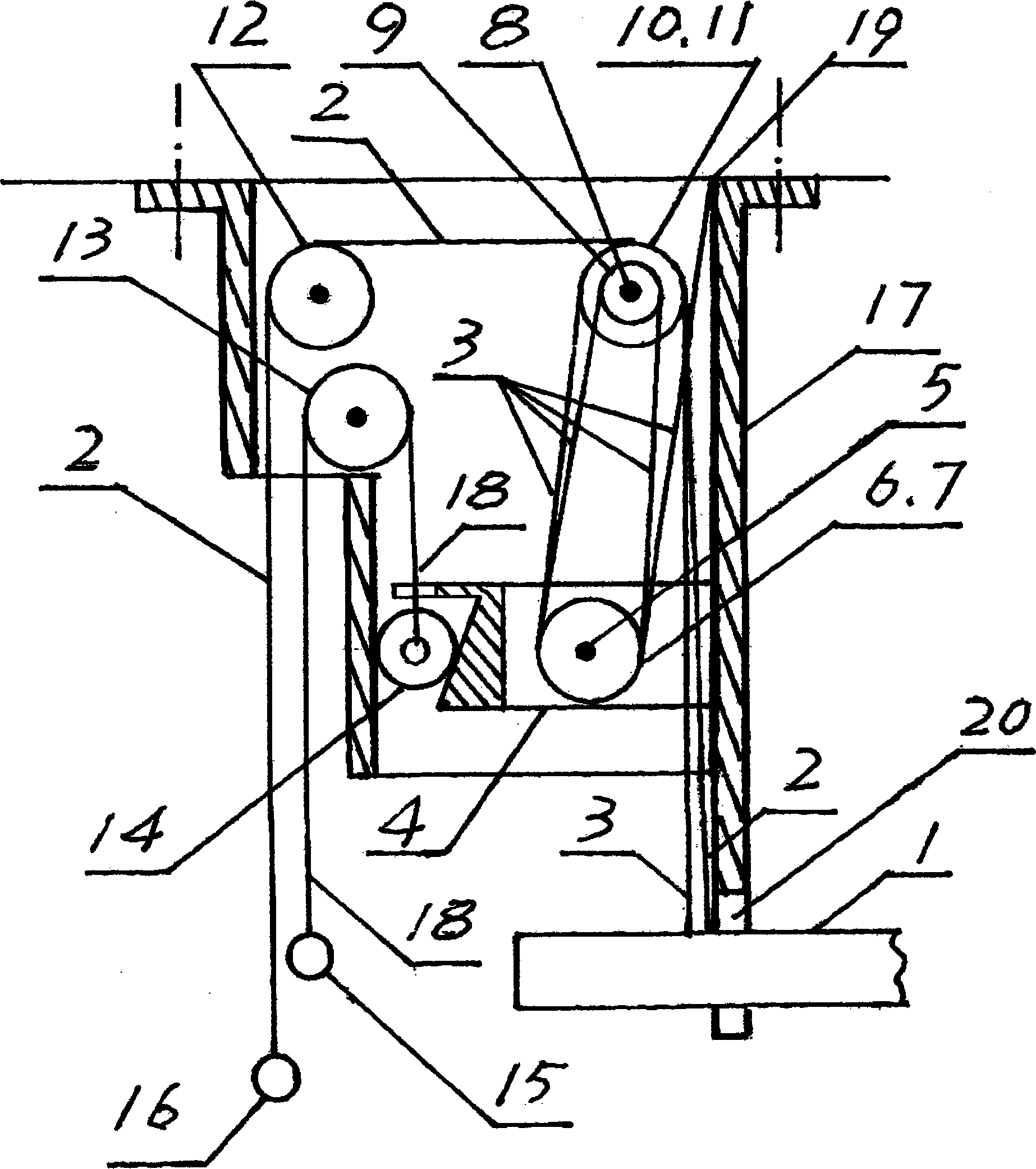
[0010] When the landing bracelet 15 is pulled downward, the control rope 18 pulls the round wheel 14 to move upward through the guide wheel 13, so that the self-locking of the inclined block 4 and the guide tube 17 is released, because the weight of the support 1 is greater than a quarter of the inclined block 4 The weight, so the downward movement of the support 1 under the action of its own weight will make the inclined block 4 move upward. When the bracket 1 falls to the desired position, stop pulling the landing bracelet 15. After the slope of the inclined block 4 touches the round wheel 14, the round wheel 14 re-engages with the inclined surface of the inclined block 4 to generate self-locking and fix the position where the bracket 1 stays. , to achieve the purpose of lowering the bracket. At the same time, because the center of gravity of the inclined block 4 is between the inclined plane and the center of the movable pulley block 5, the speed at which the inclined block...


PUM


Abstract

A self-locking descending bracket can be fixed as well as be movably descended. The bracket also has a self-locking function for preventing the bracket from falling no matter to which position the bracket is raised or descended. The present invention provides an ideal bracket which is safe for drying clothes in high-rise buildings.

Description

technical field [0001] The patent of the present invention relates to a support that can be moved up and down, especially a support that is suitable for drying clothes at home. Background technique [0002] Along with the continuous increase of high-rise residential buildings, people's traditional use for erecting clothes-drying racks has no anti-drop device, so once the support falls from high-rise buildings, it will cause great harm, so it cannot be suitable for use in high-rise buildings. It is the need to build a harmonious society to develop a rack for drying clothes that can be lifted and prevented from falling Contents of the invention [0003] In order to solve the problems that the traditional racks for drying clothes are easy to fall and inconvenient to use, the patent of the present invention provides a rack with a self-locking and lowering function that can be set according to the user's needs, and is very convenient to use. [0004] Structural principle of th...

Claims


Application Information

Patent Timeline
IPC IPC(8): D06F57/12
Inventor 程金煦
Owner 程宇鸣
Learn More