

Tetherless tube inspection system
A non-destructive inspection and drive system technology, applied to pipe components, pipes/pipe joints/pipe fittings, and detecting the presence of fluid at leakage points, etc., can solve problems such as dirty flexible shafts, large inspection equipment, and difficult inspection operations
- Summary
- Abstract
- Description
- Claims
- Application Information
AI Technical Summary
Problems solved by technology
Method used
Image

Examples
Embodiment Construction
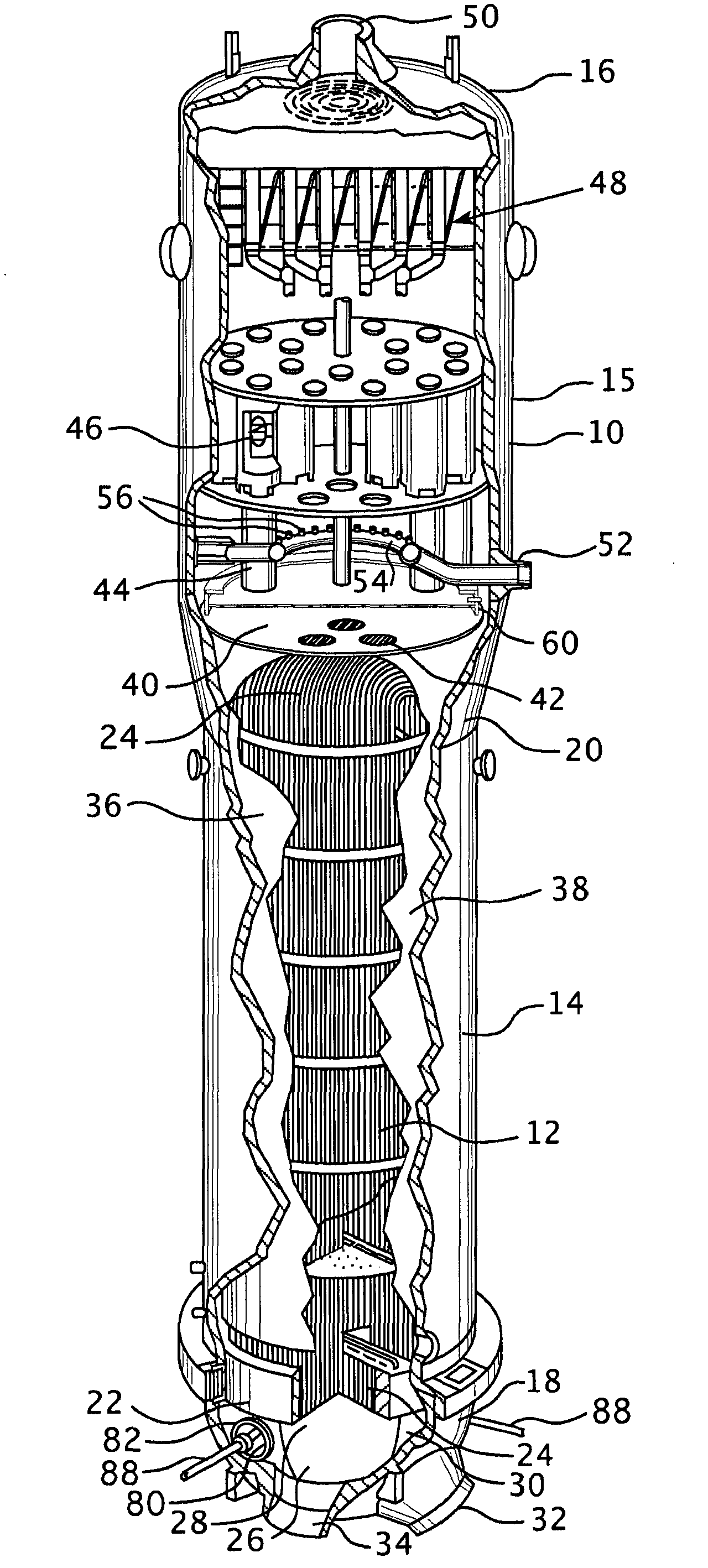
[0023] With reference to the accompanying drawings, figure 1 Shown is a steam generator 10 which utilizes a plurality of U-shaped tubes forming a tube bundle 12 to provide the heating surface required for heat transfer from a primary fluid traveling within the tubes for vaporizing or vaporizing the surrounding tube exterior. secondary fluid. The steam generator 10 comprises a vessel having a vertically oriented tubular casing with a reduced diameter lower portion 14, a conical central portion 20 and an enlarged diameter upper portion 15 and a generally hemispherical shape surrounding the lower end. The channel head 18 of the upper part is covered on top with a top casing or dish-shaped head 16 surrounding the upper end. The tube sheet 22 is attached to the channel head 18 and has a number of holes provided therein to receive the ends of the U-shaped tubes. A partition plate 26 is arranged centrally within the channel head 18 to divide the channel head into two chambers 28 an...
PUM
 Abstract
Description
Claims
Application Information