
Brake device

A brake device and wheel shaft technology, applied to vehicle parts, transportation and packaging, brakes, etc., to achieve smooth braking, prolong service life, and reduce wear and tear

Inactive Publication Date: 2013-10-30
郑佳翼
View PDF4 Cites 0 Cited by
  • Summary
  • Abstract
  • Description
  • Claims
  • Application Information

AI Technical Summary

Problems solved by technology

[0004] Patent authorization announcement number is the Chinese invention patent of CN2853471Y. The buffer device is arranged on the shaft of the driving wheel of the motor vehicle. During emergency braking, the pin shaft that closes the force component groove is opened, so that the wheel shaft slides down along the force component groove, thereby decomposing the forward sprint force into downward and upward forces, reducing the forward inertial force of the motor vehicle, although shortened to a certain extent The distance that the vehicle rushes forward after emergency braking, but it cannot achieve fast and smooth braking during emergency braking

Method used


Image

  • Brake device
  • Brake device
  • Brake device

Examples


Embodiment Construction

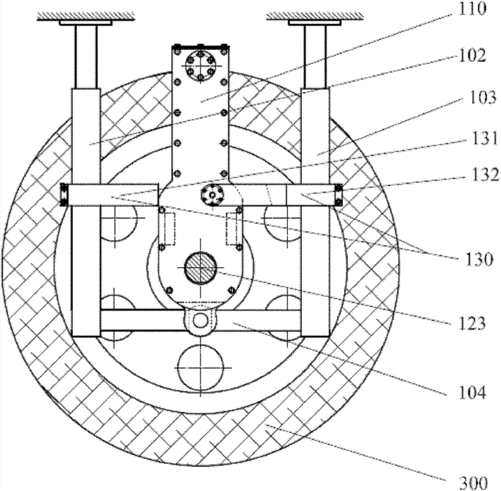
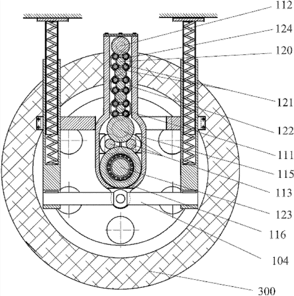
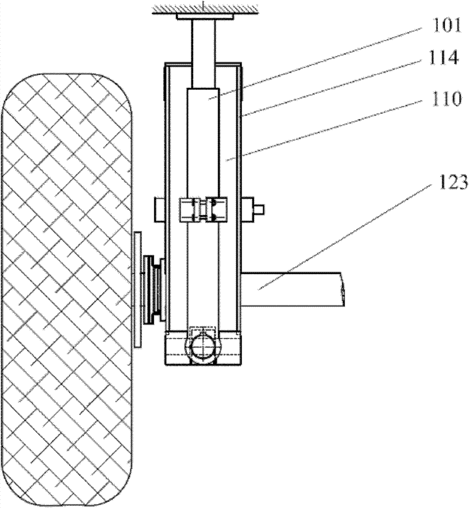
[0056] The press brake mechanism also includes a rotating sleeve 117, a fixed friction disc 118 and a movable friction disc 119 arranged outside the roller box 110, one end of the rotating sleeve 117 is connected with the transmission sleeve 116, and the other end of the rotating sleeve 117 is equipped with The fixed friction disc 118 and the movable friction disc 119 are fixedly connected to the wheel shaft 123 and rotate with the wheel shaft 123 , and the movable friction disc 119 and the fixed friction disc 118 are arranged facing each other.

[0057] The controller controls the contact and separation of the fixed friction disc 118 and the movable friction disc 119 . The weight of the vehicle body is applied to the uppermost roller 111 through the elastic member, and the weight is applied to the lower rollers 111, the speed change wheel group 113 and the transmission sleeve 116 through the uppermost roller 111, and the transmission sleeve 116 directly acts on Wheel axle 123...


PUM


Abstract

The invention relates to a brake device. The brake device comprises a pressurization brake mechanism and a controller controlling the work of the pressurization brake mechanism, wherein the pressurization brake mechanism comprises a roller box arranged on a wheel axle, the roller box is pressed on the wheel axle by an elastic component, a transmission sleeve arranged on the wheel axle through a bearing is arranged in the roller box, and a topmost layer of roller serving as a bearing wheel, multiple layers of rollers performing force transmission functions and a bottommost layer of roller serving as a speed variable wheel set are sequentially arranged above the transmission sleeve from top to bottom, wherein the axial directions of all the layers of rollers are consistent with that of the wheel axle. The brake device acts on the wheel axle and brakes a vehicle through rolling friction force, so that an brake impact on the vehicle during emergency brake can be reduced, the forward inertia force of the vehicle can be quickly reduced, rapid brake is realized, and the safety of people in the vehicle during emergency brake are improved.

Description

technical field [0001] The invention relates to a braking device, in particular to an emergency braking device. Background technique [0002] At present, various commonly used brake devices mainly use drum brakes and disc brakes. Drum brakes are equipped with two semicircular brake pads in the wheel hub, and the brake pads and the wheel hub are pushed by the piston of the sub-pump using the principle of leverage. Friction occurs when the inner surface contacts to produce braking; disc brakes are equipped with brake pads on both sides of the brake disc driven by the wheel, and the brake pads are pushed by the sub-cylinder piston to clamp the brake disc on both sides to produce braking. In the above two braking methods, the brake pads and the wheel hub or brake disc generate a large braking force through sliding friction. When the vehicle is running at low speed, it can brake safely, but when driving at high speed, emergency braking is required in case of emergency. At this ...

Claims


Application Information

Patent Timeline
Patent Type & Authority Patents(China)
IPC IPC(8): B60T1/06
Inventor 郑传远
Owner 郑佳翼
Learn More