
Equipment for manufacturing thin-walled pipe inner liner, and method thereof

A technology for thin-walled pipes and inner linings is applied in the field of manufacturing thin-walled pipe linings, which can solve problems such as burn-through, decarburization, and melting of the inner wall of pipes, so as to improve yield, improve quality, and have good mechanical impact resistance. Effect

Active Publication Date: 2013-06-26
ZOOMLION HEAVY IND CO LTD
View PDF26 Cites 0 Cited by
  • Summary
  • Abstract
  • Description
  • Claims
  • Application Information

AI Technical Summary

Problems solved by technology

This method will release a large amount of heat when the chemical reaction occurs, so it is easy to form a high temperature above 1000 ° C in the reaction chamber, resulting in local melting and decarburization of the inner wall of the pipe fitting, and burn-through will occur when the thickness of the workpiece is thin, thus limiting this method. Can only be applied to pipe fittings with thicker wall thickness

Method used


Image

  • Equipment for manufacturing thin-walled pipe inner liner, and method thereof
  • Equipment for manufacturing thin-walled pipe inner liner, and method thereof

Examples


Embodiment Construction

[0018] Hereinafter, the present invention will be described in detail with reference to the drawings and examples. It should be noted that, in the case of no conflict, the embodiments in the present application and the features in the embodiments can be combined with each other.

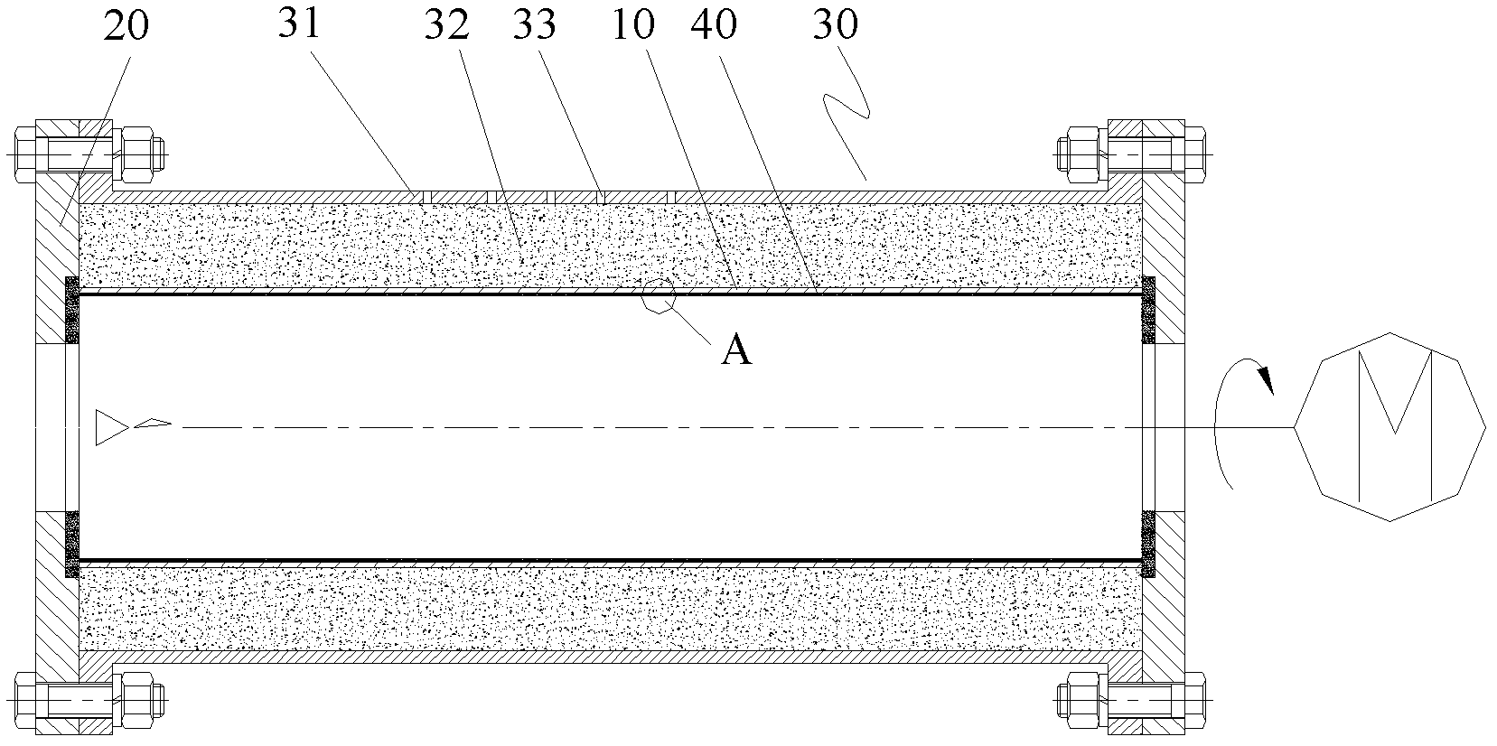
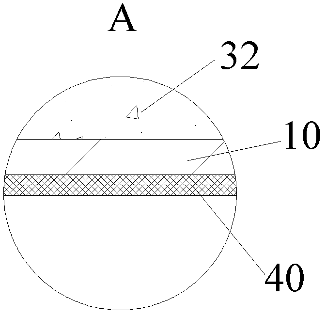
[0019] Such as figure 1 and figure 2 As shown, according to the embodiment of the present invention, the equipment for manufacturing the inner lining of the thin-walled pipe includes end caps 20 arranged at both ends of the thin-walled pipe 10, and also includes an outer barrier 30 wrapped around the outer layer of the thin-walled pipe 10. The blocking wall 30 is fixedly arranged between the end caps 20 at both ends. The outer retaining wall 30 is made of a material different from that of the thin-walled pipe 10 , and will not react with the thin-walled pipe 10 under high temperature conditions, nor will it be bonded to the thin-walled pipe 10 under the influence of high temperature.

[0020] The...


PUM


Abstract

The present invention provides equipment for manufacturing a thin-walled pipe inner liner, and a method thereof. The equipment for manufacturing the thin-walled pipe inner liner comprises end covers (20) arranged on both ends of the thin-walled pipe (10). The equipment further comprises an outer block wall (30) arranged on the outer layer of the thin-walled pipe (10), wherein the outer block wall(30) is fixedly arranged between the end covers (20) of the both ends. According to the equipment for manufacturing the thin-walled pipe inner liner, the wear resistant layer can be formed on the inner wall of the thin-walled pipe, such that the damage to the thin-walled pipe can not be generated, the production cost is effectively reduced, and the yield is improved.

Description

technical field [0001] In particular, the present invention relates to a device and method for manufacturing the inner lining layer of thin-walled pipe fittings. Background technique [0002] In the field of loose material pipe conveying, the service life of conveying pipe fittings directly affects the working efficiency and operating cost of conveying equipment. In order to improve the service life of loose material conveying pipe fittings, it is necessary to strengthen the wear resistance of the inner wall of ordinary conveying pipe fittings to form a wear-resistant layer. The self-propagating high-temperature synthesis (hereinafter referred to as SHS) method is one of the methods for cladding the wear-resistant layer on the inner wall of the conveying pipe. Currently, the commonly used SHS methods include centrifugal method and gravity method. [0003] The SHS method is a method that uses the heat released by the chemical reaction of the cladding raw material after local...

Claims


Application Information

Patent Timeline
Patent Type & Authority Patents(China)
IPC IPC(8): C23C24/10
Inventor 樊兴胜
Owner ZOOMLION HEAVY IND CO LTD
Learn More